Usually a better match can be obtained with individual self bias resistors, and individual bypass caps.
The connections could be something like this:
Ground
Grounded secondary tap
'Hot' Secondary tap
Individual bias R & C (- on C)
Individual bias R & C (+ on C)
Individual cathodes.
Be sure to account for the extra Miller Effect Capacitance.
The driver has to slew 2X the current for 2 parallel tubes.
Not so much for Pentode mode or Beam Power mode.
Can be quite a bit for Triode Wired mode (the screen is near g1).
The factors only multiply when you parallel 3, 4, 5, tubes etc.
More power supply current, stronger driver, etc.
Calculate the output transformer for 1 tube.
Then re-calculate accordingly:
Divide the primary impedance by the number of parallel tubes.
Divide the primary DCR by the number of parallel tubes.
Multiply the required laminations by the number of parallel tubes.
That gives the required output transformer specifications.
Good luck with the project. Let us know how it sounds, please.
Last edited:
I'm not sure that matching is mandatory. I hate those kinds of designs anyway. They tend to lead to one tube red-plating later as the tubes age and mismatch occurs.
Personally, I'd do separate fixed bias per output tube and separate sense resistors for adjusting each tube's bias, then I'd check them every so often.
Personally, I'd do separate fixed bias per output tube and separate sense resistors for adjusting each tube's bias, then I'd check them every so often.
Individual RC self bias networks also serve as sense resistors. Surprise!
With a common cathode feedback winding, and sense resistors (or with self bias resistors),
the test points are across the resistors. The resistors do not connect to ground; so there are 2 test points per resistor to read the voltage and to calculate the current.
There is no 'fooling mother nature here'.
And, as the tubes age, they tend to age more closely, the self bias tends to self adjust.
Of course if you have a bad tube in the bunch; then using adjustable fixed bias will not make a bad tube into a good tube.
There is one way to fix a bad tube . . . replace it as soon as you notice it is bad.
Perhaps the red plating occurs more often with fixed bias, than with self bias.
And, you have to meet the specs for the maximum g1 grid resistor, or red plating can occur.
More g1 in parallel, reduce g1 resistor according to the number of parallel tubes.
Failing to pay attention to all the details can make the parallel design sound bad, age prematurely,
or just fail to function.
Do you think perhaps that poor design practices and in-attention to details might explain why parallel tubes gets such a bad reputation?
Do it the right way . . . Success.
Just my 2 cents worth.
Last edited:
Just one more thing to add about parallel tubes.
Mismatched tubes give higher distortion.
The same goes for push pull tubes (and push pull output transformers Love matched DC current).
I always purchase matched tubes.
I only use 2 vendors, no others.
One of them does the very best matching (I use them, unless it is a tube type that they do not sell).
I always use self bias.
Everything comes out well.
Oh, yes, I have designed some bad amplifiers, but those got parted out.
Last edited:
Perhaps the red plating occurs more often with fixed bias, than with self bias.
The only amp I have ever owned with red plating issues was a Fisher amp with a common self bias resistor for all 4 output tubes. Terrible idea. The manual states that a matched quad is necessary. I had two separate quads that eventually caused one of the four to red plate. Then I fixed the amp so that it wouldn't do that anymore.
I'm not a fan of self-bias myself, but if you must do it, use separate resistors for each tube. I just hate the waste of self-bias and the fact that the bypass cap is going to cause non-ideal behavior.
I don't just use fixed bias when I build an amp, but the bias is adjusted by a servo so it never needs attention. I also have circuitry to monitor output tube current and cut amp power in over-current situations. But that's my preference.
6АЗsUMMER, thanks! I was pretty much aware of the other specifics you described. Yes, distortion increasing with tubes mismatch makes sense.
I will try going for pentode mode with UL + CFB, so input capacitance won't be much of an issue. Just looking for a 4P1L LTspice model to verify it. Some tubes aren't meant for CFB + UL.
Will probably go for a mixed (cathode + fixed bias) route, + voltage meter with switch to look across each cathode resistor's current.
Folks say 4P1Ls are easy to match. Mines are from a same production period. What's your opinion?
I'm creating my own transformers, so no issue with the OPT calculation and design.
I think you'd be surprised how little difference in distortion matching or not matching would make if you have a system to ensure proper bias of both tubes. In push-pull it would be more obvious, but I don't think it would make much difference in SE unless one of the two is just terrible compared to the other.
If they are both linear, but different, they are just going to blend into something linear but a composite of the two.
If they are both linear, but different, they are just going to blend into something linear but a composite of the two.
With parallel tubes, a mismatch can cause distortion when one goes into cutoff early.
And, with parallel tubes, a mismatch can cause distortion when one has a different fixed bias voltage, and so it draws grid current early.
Just a couple of examples.
The cover article of the very last issue of Glass Audio ("Paralleling Tubes Effects") covered that, and much more too.
I have never even seen a 4P1L, and so I have never used one.
No experience, no opinion (in this case).
Last edited:
With parallel tubes, a mismatch can cause distortion when one goes into cutoff early.
And, with parallel tubes, a mismatch can cause distortion when one has a different fixed bias voltage, and so it draws grid current early.
Just a couple of examples.
The cover article of the very last issue of Glass Audio ("Paralleling Tubes Effects") covered that, and much more too.
I have never even seen a 4P1L, and so I have never used one.
No experience, no opinion (in this case).
Sure, clipping behavior will change, but clipping is going to be ugly anyway. Remember, this is an SE amp, so mismatch will likely soften clipping as one tube clips and the other is left holding the bag so to speak, right before it clips too. I mean, match if you want to but I think mismatched 4P1Ls will sound great too, as long as they are both properly biased.
Now push-pull is another story altogether.
SpreadSpectrum,
As you know, I always say, if it is clipping, turn the volume down or get a more powerful amplifier.
Badly matched tubes, even in single ended will cause less power,
because one tube will clip early
and because on tube will cut off early
What was also mentioned in "Paralleling Tubes Effects" was the extra distortion, even before clipping and before cutoff, when the tubes were not well matched.
A pair of self biased triodes had a 1.12:1 difference in current. Not too good, not too bad.
When those same tubes were paralleled, the differences in current was 2.16:1. That was because, when they were paralleled, the individual self bias resistors were paralleled (by the cathodes being tied together; and also when the plates were paralleled together the plate load resistors were also tied together).
12% difference seemed OK, but over 100% difference showed the problem with not using individual bias.
Not paying attention to bias, whether fixed or self bias, can cause major problems.
Last edited:
I don't disagree with anything you are saying. It is all a matter of degrees. Maybe I've been lucky in this hobby so far but I haven't had a difference of 12% between two tubes when new. That's where I was coming from when I made my initial remarks.
I really don't think I'd be able to tell the difference between a perfectly matched pair and a 5% mismatch in a PSE amp, especially if clipping is avoided. That's what I'm trying to say.
I really don't think I'd be able to tell the difference between a perfectly matched pair and a 5% mismatch in a PSE amp, especially if clipping is avoided. That's what I'm trying to say.
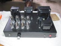
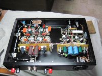
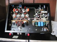
Tony,
Looks great!
And I like your pcb to mount the individual self bias resistors and bypass caps on.
That is what I see in the picture, Right?
Thanks for that testimony.
yes individual cathodes with individual resistors and bypass caps, 250v plate and 30ma cathodes...on the left hand side of the picture...
the board on the right hand side are dc filament supplies...
I'll weigh in with my tiny experience of parallel SEP amplifiers WRT matching and distortion.
I have used 1, then 2, then 3, and 4 small tubes in parallel for a small SE amp I built using russian 6P30B-R (theres a thread somewhere here about it, which I cant be bothered to point out but can be found if searched)
These tubes are a twin anode 7W pentode/beam pentode, and I was aiming for 1W out with a single device. I got about 0.8W. So I paralleled.
First I tested all tubes in the real circuit, and noted the anode volts and current.
Span of results was easily +/-40%, maybe more.
Using "unmatched" devices with a difference in op point, of more than 10% did indeed increase distortion at 2x Pout, meaning I could realise perhaps 1.5x Power using 2 valves. In particular, the spectra of THD was different, I'd say, worse. Attempting to bias each device to the same op point, improved things, but leads to one device carrying the other, and the results not as good as those that start out closer in op point, with a fixed cathode circuit.
Matching to less than 10% difference, lead to almost identical performance to a single valve, but at 2xPout
Eventually realising equivalent THD performance at closer to 1.8x power for 2 devices in parallel.
In all cases, each device had it's own cathode self bias network, and a shared screen supply, bypassed locally to each device.
So there is definitely something to matching, but perhaps the nth degree is not necessary.
Last edited:
Span of results was easily +/-40%, maybe more.
Using "unmatched" devices with a difference in op point, of more than 10% did indeed increase distortion at 2x Pout, meaning I could realise perhaps 1.5x Power using 2 valves. In particular, the spectra of THD was different, I'd say, worse. Attempting to bias each device to the same op point, improved things, but leads to one device carrying the other, and the results not as good as those that start out closer in op point, with a fixed cathode circuit.
That span surprises me a bit.
The lower paragraph is what I'd expect. Something that comes to mind is the dual-plate construction of some 2A3s. I wonder if this is an issue with some of them, or if consistency is easier to achieve in low gm triode devices.
My limited experience with low gm DHTs is that they are pretty consistent. My quad of 841s have very close grid bias voltages to achieve the same operating point.
Never tried parallel tubes with single CFb winding. To be honest I have not even tried in a SE.
In PP where each tube has to have its own winding for obvious reasons I can tell you that for each 1 dB of feedback you get 2 dB (or close) reduction in distortion. So it works great also with less sensitive pentodes like a 6F6 for example. Probably if you have separate windings you might get benefit in reducing the effect tubes mismatch on distortion but this is something you have to try....
In PP where each tube has to have its own winding for obvious reasons I can tell you that for each 1 dB of feedback you get 2 dB (or close) reduction in distortion. So it works great also with less sensitive pentodes like a 6F6 for example. Probably if you have separate windings you might get benefit in reducing the effect tubes mismatch on distortion but this is something you have to try....
- Status
- This old topic is closed. If you want to reopen this topic, contact a moderator using the "Report Post" button.
- Home
- Amplifiers
- Tubes / Valves
- CFB for tubes in parallel, PSE. Any surprises?