I am thinking about the loadline of 300B and there is a website which provide handy calculation on loadline on various tubes.
But there is a question I don't understanding, is that the maximum plate voltage limited to the HT provided? For example, if the HT is only 500v than the 300B would only reach 500v plate voltage at max swing?
But there is a question I don't understanding, is that the maximum plate voltage limited to the HT provided? For example, if the HT is only 500v than the 300B would only reach 500v plate voltage at max swing?
Attachments
Typically, the load on the 300B is either an output transformer,
Or a plate load choke (in a Parafeed circuit).
Both of those cases can have the plate swinging to 2X B+, or 1000V.
You typically do not want a resistor to be the load for a 300B (unless it is used as a driver for a more powerful output tube; so use a choke or output transformer).
By the way, the original specification for quiescent plate voltage of the Western Electric 300B during the 1930s was 450V, not 500V.
Last edited:
Hi januaryabc,
when going to this page: Universal loadline calculator for vacuum tubes - Vacuum Tube Amplifiers - DIY
be sure you select "reactive" load, not "resistive".
when going to this page: Universal loadline calculator for vacuum tubes - Vacuum Tube Amplifiers - DIY
be sure you select "reactive" load, not "resistive".
"Swing to???" Remember it *starts* at 500V DC, no signal applied.I understanding the 300B should mostly connect to the output transformer which one end should connect to a filtered HT supply. Suppose that end can provide only 500V, is that the 300b can only to swing 500V only?
It also *starts* passing a certain idle current walue.
That´s why Class A amps run so hot: even without signal they are already dissipating full +V and significant idle current: lots of (wasted) watts.
If it gets a positive signal at the grid, it will increase that idle current even more, up to double, and at the same time that extra current will drop plate voltage because it will drop across plate load impedance.
At peak signal and current, plate voltage will drop towards 0V.
Never reaching it, of course, because tube plate can only reach a certain minimum voltage, called saturation voltage.
So IF saturation voltage is, say, 50V, plate will swing down -450V (500-50)
So far so good, but this is Audio, so now that AC signal will swing the other way, symmetrically, so on negative peak plate will be almost cutoff (0 mA) and its voltage will be "the other" way from 500V.
Yes, 500+450=950V

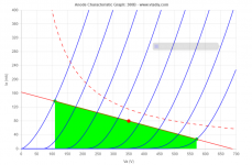
Perhaps best to start with your initial post and the plotted load line. If that represents your SE output stage, and the 'dot' on the loadline represents your idle voltage and current, then you have a 350V B+ feed with 80mA of idle current. That loadline of 700V at 0mA and 160mA at 0V represents 4.3kohm, which is the transformer turns ratio reflection of the load resistor on the speaker output. The green section represents the anode being forced to swing down to 110V due to a grid voltage signal around its bias voltage level, and the anode voltage change of 350-110=240V (represented as a peak voltage swing) but it may be better to think of that as a swing in 300B current from 80mA to 140mA. The grid voltage is an ac signal and will swing the other way and for a sinewave will continuously control the anode current down from 140mA to 30mA, and the 300B voltage (Vak) will rise to 570V, which is a 570-350=220Vpk swing from idle level, so the total primary voltage is circa 460Vpp - that voltage is turns ratio transferred to the speaker resistor and power is calculated from an rms conversion of Vpp to Vrms.
There are many good articles that you really should seek out and get to understand. Especially to appreciate what happens as the plate approaches any limit (such as grid conduction, or cutoff) and what a reactive load does to the load line.
There are many good articles that you really should seek out and get to understand. Especially to appreciate what happens as the plate approaches any limit (such as grid conduction, or cutoff) and what a reactive load does to the load line.
A class A SE amplifier has a steady voltage and steady current when there is no music playing, and no test signal either.
This is called the Quiescent state.
Let's design an SE amplifier to have the quiescent state with the 300B's plate voltage at its maximum quiescent rating of 450V.
Set the 300B grid bias so that the plate current is 50mA when the plate is at 450V.
450V @ 50mA is 22.5 Watts of plate dissipation. That is the quiescent state.
So we have 50mA of current in the primary inductance of an output transformer.
Inductance has a special characteristic, it maintains the current that it has passing through the windings.
When signal is applied to the 300B grid, it causes the 300B to draw more current, and to draw less current, according to the polarity of the signal. A sine wave has equal + and - polarity voltage.
When the polarity goes negative (-), the 300B conducts less current.
But the output transformer primary inductance will attempt to continue to pass 50mA.
The difference in quiescent current that the primary had, and the new lower 300B current with signal applied has to go somewhere. The output transformer magnetic field partially collapses, causing secondary current to be passed to the loudspeaker.
Since the primary is trying to maintain the 50mA current, its voltage raises as high as 2X B+ (2 X 450V = 900V).
By the way, when the signal that is applied to the 300B grid goes positive (+), the 300B draws more plate current. But the output transformer primary inductance is trying to maintain 50mA. So, the magnetic field increases, and the secondary passes the extra current from the 300B on to the output transformer secondary, and on to the loudspeaker. If it were possible (it is not quite possible) the plate would go to zero volts (0V).
This is an output transformer and a 300B. A 5k Ohm to 8 Ohm transformer has 25 times more turns in the primary than in the secondary, 25:1.
So, if the 300B plate goes from 450V to 900V (a difference of 450V), then the primary voltage changes by 450V.
The secondary voltage change is 450/25 = 18V.
And when the signal to the 300B grid goes positive (+), the 300B draws more current, and the plate voltage (and primary voltage) goes down.
In real operation, and with a loudspeaker load, the 300B plate will not go down to zero volts, and will not go up to 900V.
I used to describe an SE amplifier as the output tube and output transformer are using up power all the time, even with no signal applied.
But when signal is applied, they pass some of that power on to the loudspeaker (and keep a little less power for themselves).
Hopefully you get the general concept of how a single ended amp triode and output transformer works.
Last edited:
Yes. It comes from inductance.Is that comes from the transformer?
- Status
- This old topic is closed. If you want to reopen this topic, contact a moderator using the "Report Post" button.
- Home
- Amplifiers
- Tubes / Valves
- AC loadline and max output