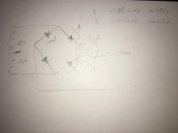
I am trying to design a power supply which could provide over 700V DC and would like to employ some form of slow start in order to put less stress on power tubes. But it seems there is no tube rectifier which can withstand such voltage. I noted from Morgan Jones’s Valve Amplifier that diode could be added in series to increase voltage rating, with capacitor added in parallel to keep even distribution of voltage across them. And so I drawn the following circuit to try to limit the AC voltage across the tube rectifier. Is my design feasible? Is there a better way to employ tube rectifier with such a high HT voltage? Thanks.
Attachments
One method is as suggested to use a ss bridge with your 2x280V = 560V secondary, and put a normal or damper valve diode in the pos output leg of the bridge, and then feed your filtering caps. A variation of that is to use some initial capacitor filtering after the bridge, and then insert the valve diode before a second batch of filter caps to provide B+.
In those situations the ss diodes manage the rectification PIV requirement, and the valve diode just sits at the B+ level (so no issue for heater or PIV when compared to a typical 5V diode like a 5U4 with parallel connected anodes). The subtle differences are power supply in-rush current levels with either a cold or hot valve diode, and the voltage drop from the valve diode.
But perhaps worth going back to your original assumption that a valve diode is needed to 'put less stress on power tubes' - can you elaborate on what exactly is your concern and how you came to consider that was significant enough to force you to consider modifying your power supply?
Member
Joined 2009
Paid Member
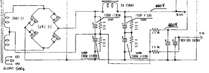
Here is another example of using a damper diode, the 6da4, for slow warm up.
This schematic is by JC.
And probably wise to bypass the 6da4 with a 4K resistor of a suitable size.
stay safe
t
Why is it wise to bypass the 6DA4 with a 4K resistor? Would it not cause the voltage on the plate and the screen grid of the 6L6 to be something like 650 V during warm-up while its cathode is still at 0 V? Or is this no problem for a 6L6?
One method is as suggested to use a ss bridge with your 2x280V = 560V secondary, and put a normal or damper valve diode in the pos output leg of the bridge, and then feed your filtering caps. A variation of that is to use some initial capacitor filtering after the bridge, and then insert the valve diode before a second batch of filter caps to provide B+.
In those situations the ss diodes manage the rectification PIV requirement, and the valve diode just sits at the B+ level (so no issue for heater or PIV when compared to a typical 5V diode like a 5U4 with parallel connected anodes). The subtle differences are power supply in-rush current levels with either a cold or hot valve diode, and the voltage drop from the valve diode.
But perhaps worth going back to your original assumption that a valve diode is needed to 'put less stress on power tubes' - can you elaborate on what exactly is your concern and how you came to consider that was significant enough to force you to consider modifying your power supply?
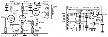
I am designing a 300b se with all tubes dc coupled. Would someone comment the feasibility of the circuit? I guess a CCS is required in the cathodes of tubes to help controlling the drifting of operating point due to tube ageing.
Attachments
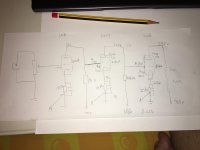
I would be more concerned about the voltage difference between the grid and the cathode of the 300B during start-up (365 V), but I have no experience with the 300B and I do not know of any data(sheet) for the 300B in which there is a maximum given for this voltage difference.
I would also think that the three different tubes could/will not warm up in exactly the same time. In this fully dc-coupled amplifier this could give problems. If the 300B conducts earlier than the 6SN7, it's grid would still be at 365 V.
A delay looks like a good plan to me.
Addition: If the lower B+ values (365 V & 100 V) would be created by voltage drops over resistors starting at the 755 V point in the power supply, the grid voltage of the 300B (and the voltage difference between grid and cathode) would even be 755V at start up and without delay.
Last edited:
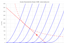
It is why I am asking suggestion on tube rectifier for this amp as I want to slow start the voltage and current applied to the tubes. I am now thinking whether it is possible for the grid of 300b or 6sn7 to become positive as compare to the cathode during the slow start and whether this will bring any harm to the tubes. I guess even when it is the case when the amp is during slow start of the tube rectifier, the positive grid will not bring harm as the operating point will always be lower than the full powered setting ( as set by the original HT and cathode bias setting), which should always below the max dissipation curve. Is that correct?
Attachments
I don't think I understand your question exactly.
I would think that if the delay is long enough, so all the tubes in the amplifier are warmed up before any B+ is there, then you will not have any problems. The tubes are than ready to quickly go to the working points you've calculated (I did check your voltages with Ohms Law, but I didn't check the working points against the datasheets; I would not know if a fully dc-coupled amplifier like this would stay stable over time but there must be other forum members who do know).
I don't have experiences with the damper diodes others already mentioned, so I don't know how long it takes them to start to conduct. I did use the PY81 as a delay more than once. It takes a PY81 about 50 (older production) to 30 (newer production) seconds to conduct. But one PY81/EY81 is probably to feeble for your needs (max. 150 mA), but I think two of them (as one half of a bridge rectifier) might work.
Last edited:
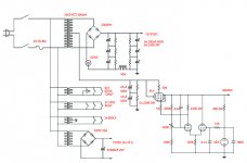
Some DC-feedback could help.I am designing a 300b se with all tubes dc coupled. Would someone comment the feasibility of the circuit? I guess a CCS is required in the cathodes of tubes to help controlling the drifting of operating point due to tube ageing.
How about this ?
Mona
Attachments
It seems that the simple addition of a protection ss diode on the 6SN7 grid to cathode, and on the 300B would suppress any concern about high positive bias levels at power turn-on due to sequencing of the different B+ rails, and conduction delay differences of the 3 valves. With that setup, I'd think the worst case would be a relatively slow 6SN7 turn on, such that the 300B bias sat around 0V for some seconds, although increased 300B conduction would be alleviated by a rising cathode voltage so perhaps not too significant.
The 300B has > 800V across it during normal operation due to signal swing. I don't see that as a stress per se.
Any other stresses?
The 300B has > 800V across it during normal operation due to signal swing. I don't see that as a stress per se.
Any other stresses?
Some DC-feedback could help.
How about this ?
Mona
This seems a smart way to control the previous stages cathode bias by the power stage. Definitely would be my way forward to improve my circuit. Thanks.
- Status
- This old topic is closed. If you want to reopen this topic, contact a moderator using the "Report Post" button.
- Home
- Amplifiers
- Tubes / Valves
- Using tube rectifier to as slow start in HT over 500V