My hearing is also not good. And Clean supply is always preferable. I will strictly follow your advice. Will purchase caps/resistors tomorrow.
Cant wait to get on filament supply and main amplifier once this main PS is OK.
Best regards.
Cant wait to get on filament supply and main amplifier once this main PS is OK.
Best regards.
hello,
I visited the shop. 100uf 450v caps were not available. 330 ohms resistor was in quarter watt and 10 watt. Due to travel restriction the shop owner will restock itmes in 10 days.
So I purchased 180ohms in 1 watt. So hope 180+180 ohms will give 2W and 360 ohms. Is that ok ? I have not soldered the parts as shop owner will take back if I dont use them.
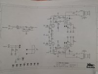
I also have 33uf 450V in my bin. They were for my valve radio repair. Will they work Just for Voltage testing purpose ? The first 220K||100uf in series with another 220K||100uf will remain same. as shown in pic.
kindly tell
I visited the shop. 100uf 450v caps were not available. 330 ohms resistor was in quarter watt and 10 watt. Due to travel restriction the shop owner will restock itmes in 10 days.
So I purchased 180ohms in 1 watt. So hope 180+180 ohms will give 2W and 360 ohms. Is that ok ? I have not soldered the parts as shop owner will take back if I dont use them.
I also have 33uf 450V in my bin. They were for my valve radio repair. Will they work Just for Voltage testing purpose ? The first 220K||100uf in series with another 220K||100uf will remain same. as shown in pic.
kindly tell
Attachments
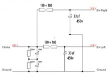
180+180 Ohm is fine. But I advise against using single 450V capacitors (in all of the B+ rail).
The artificial load makes shure that when you are testing, the choke right away does its 'swinging' so the voltage settles on the 330 V you measured. But when this power supply is feeding your amplifier, this artificial load will not be there. Because the tubes need some time to heat up, they will not pass current right away. So during heat-up the choke will not do its 'swinging'. During that time the voltage after the choke will be the same as the voltage before the choke.
In post #17 you wrote that the voltage at the bridge rectifier is 350 V. I don't really understand that because I thought that you were going to try using 2 pairs of diodes as a full-wave rectifier (so one pair connected to one of the two outer connections of the HV winding, the other pair to the other outer connection of the HV winding, and the centre-tap to ground). Anyway, this voltage of 350 V can't be right if the choke is really swinging. It should be way higher, but maybe your measurement is the result of your multimeter having difficulty with measuring a dc-voltage with a very large ripple on it (its a 'pulsating' dc voltage, going from zero Volt to some top value and back to zero Volt again, and that 100 times a second, so at 100 Hz if your mains frequency is 50 Hz).
Addition: You are writing about voltage testing with the 33 uF capacitor. Testing only that serves no purpose unless you would do it without the artificial load you are using now, combined with using two artificial loads after the 33 uF capacitor, with each load having half the resistance of the load you are using now. But there is no use in testing this. You can rely on Ohms Law in this matter.
Last edited:
OK understood. I will wait for proper value caps then.
---------------------------------------------------
Regarding Post #17 :
First I tested like this - ON Secondary of transformer the Center tap as ground. The two remaining leads had single diode each. the other two ends of diodes were shorted and connected to choke. That way I got 350v.
Then I put in one more diode in series with final voltage remaining same. I have not dismantled that setup. Will test again and post just to confirm.
regards.
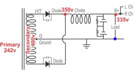
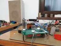
OK. I tested again. I am also attaching pic of circuit and points where voltage measurements were taken.
Primary (at primary leads) = 242v AC
Secondary (at Secondary leads) = 400v AC
After rectification (+ve multimeter lead at) Choke point shown in red (-ve lead of mm at ground shown with blue dot) = 350v
At Load shown in red dot near B+ letter and ground at blue dot) = 335v.
... B U T...W A I T...
Power Transformer misery ends. 🙁
This 50 year old power trasformer gave out smoke. The test took hardly two minutes. Earliear when I tested few times the PT was cool as cucumber. Choke (Potted) was also cool. The load resistors were warm but not hot. So looks like old wire varnish gave away. Dont know. So will see if rewinding it is worth OR probably go for new one. Buying new one is easy but I will not learn new things. Will see if other simple alternatives are possible
will update soon.
Attachments
Last edited:
Hello all,
I sincerely hope I had nothing to do with PCL200 disabling his membership. 😱 If so I apologize.
Newbie pl be gentle.
I have been reading up on power supply, RH84 Amplifier etc. Power supply impedance, ideal values of power supply components. Some questions arose...
Since now I will be custom making (off the shelf not available here) power transformer I have decided to separate HV tranaformer and filament transformer.
In original RH84 schematic the B+ supply for both channel is common and transformer is center tapped. and PCL200 suggested to avoid filter capacitor sharing between two channels so how to go about it ?
1) Can RH84 with minor changes be converted to Triode amp without feedback ? (Asking future mods)
2) I can make custom PT with two separate secondaries with appropriate VA.
3) Any advantage of having Center tap PT ?
4) I have old USA made 14H choke which I was using. But since earlier transformer mishap occured. Should I use this old choke safely ? It is potted, (Chicago standard transformer corp) with dimension (6.5cmx6cmx9cm) Looks like it can pass RH 84 current 100mA. And I read choke filter gives good voltage regulation.
5) After deciding if to use Choke filter OR RC filter, Transformer; will need to know transformer voltages and VA ratings. So in short pl give best solution for both (1) Choke filter supply (2) RC filter supply. Transformer windings, Center tapped or not, VA ratings.
Thanks and regards.
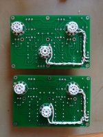
RH84 in test
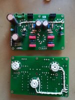
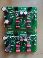
My version of PCB for RH84 in test,
My version of PCB for RH84 in test,
Attachments
Last edited:
Thats Neat build. From 230v secondary how much B+ you are getting ?
thanks very much for sharing.
thanks very much for sharing.
Hello everyone,
A friend's friend who is in transformer business has offered to help me. So now I can afford the luxury of having separate filament and separate power Transformer at very good price. He has asked my requirements. so pl. guide me.
1) I would like to use 14H single choke that I already have. It will be like this.
supply from Secondary windings >> Solid State Rectifier >> CLC (Correct me if I am wrong) Will that be OK ?
2) considering above what should approximate Secondary Voltage be ?
3) Will it help if I make Two separate secondary windings for two channels ?
4) I will have One extra transformer with separate secondaries for Heater Filaments of EL84 and 12AT7. And would like AC but with regulation (We have mains fluctuation). For LM317 AC voltage regulator what should be secondary voltages so that I get final 6.3v under load?
5) Should filament supply be centertaped for exampls V-0-V with Center tap to ground OR Should it be Floating like 0 - V ?
Newbie here please be gentle. 😱
Regards
- Home
- Amplifiers
- Tubes / Valves
- Can I make RH84 from these parts ?