Found another vintage tube console that seems like a good candidate for converting into a standalone amplifier. I really like these old vintage consoles for honing my soldering and chassis modding skills. They usually come very cheap (sometimes free) and the accessible point to point wiring makes them fairly noob friendly.
Here's what I've done so far:
- removed the pre-amplifier / tuner section
- added polarized power cord, on/off switch, and fuseholder
- replaced all power filter caps (kept old capacitor cans for aesthetics)
Please note that all the tone controls, etc. are removed along with the pre-amplifer section. The pots and switches were not worth cleaning and using.
What should I do with the rest of the circuit to use it as standalone amplifier and have it sound good? Is it as simple as replacing the coupling caps as per the schematic? Or are other values or modifications recommended?
Any guidance much appreciated. Schematic attached.
Attachments
Well, I guess I'd just bring it up to original health and enjoy the couple-few watts of single ended tube amplification.
Check the carbon composition resistors to see if any have drifted waaay off - you know about replacing the power supply and coupling caps already. If you find a similar vintage push-pull 6BQ5 amp, you could bring that one back to stock - and keep the two amps for a sound comparison shootout with your friends. They will certainly sound different -
Check the carbon composition resistors to see if any have drifted waaay off - you know about replacing the power supply and coupling caps already. If you find a similar vintage push-pull 6BQ5 amp, you could bring that one back to stock - and keep the two amps for a sound comparison shootout with your friends. They will certainly sound different -
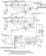
I will not pull punches. The "Electrohome" unit is a PoS.  The schematic shows circuitry that's unsafe, non-linear, and exhibits poor voice coil control (damping factor).
C19 is an instance of the notorious "death" capacitor. The O/P tubes are in full pentode mode and no NFB is present. Hence, distortion and a high O/P impedance are present. YUCK!
Because the power transformer had to energize things other than the O/P section, it appears to be competent. The 6CA4/EZ81 rectifier can handle up to a 150 mA. draw and would not be present, if a less capable type was remotely up to the task.
Salvage the power transformer, and tubes (if still good). A 12AX7 section as voltage amplifier and full pentode 6BQ5/EL84 "final" gets you approx. 5 WPC. You need a global NFB loop and decent O/P "iron". Edcor's GXSE15-5K meets the requirements and will give you good bass extension, courtesy of mass and the NFB.
The schematic shows circuitry that's unsafe, non-linear, and exhibits poor voice coil control (damping factor). C19 is an instance of the notorious "death" capacitor. The O/P tubes are in full pentode mode and no NFB is present. Hence, distortion and a high O/P impedance are present. YUCK!
Because the power transformer had to energize things other than the O/P section, it appears to be competent. The 6CA4/EZ81 rectifier can handle up to a 150 mA. draw and would not be present, if a less capable type was remotely up to the task.
Salvage the power transformer, and tubes (if still good). A 12AX7 section as voltage amplifier and full pentode 6BQ5/EL84 "final" gets you approx. 5 WPC. You need a global NFB loop and decent O/P "iron". Edcor's GXSE15-5K meets the requirements and will give you good bass extension, courtesy of mass and the NFB.
Using grid leak bias on the input tube is not a great way for consistent performance, nor for low distortion performance.
Put a self bias resistor and bypass cap from the input tube cathode to ground.
Repeat for the other input tube cathode.
Most modern signal sources have very small DC offset voltage.
And most modern signal sources can drive 10k loads.
So get rid of all that input circuitry.
Use a 50k pot for volume control, and a 1k grid stopper at the input grid.
That will keep the input tube Miller Capacitance at bay (50k versus 1Meg input pot).
And get rid of that cap from the input tube plate to ground (cuts off high frequencies).
Just like Eli said, get a decent output transformer, and add some negative feedback.
When you take out C19, take out R23 too.
Just my opinion.
Last edited:
I will not pull punches. The "Electrohome" unit is a PoS.
C19 is an instance of the notorious "death" capacitor. The O/P tubes are in full pentode mode and no NFB is present. Hence, distortion and a high O/P impedance are present. YUCK!
Because the power transformer had to energize things other than the O/P section, it appears to be competent. The 6CA4/EZ81 rectifier can handle up to a 150 mA. draw and would not be present, if a less capable type was remotely up to the task.
Salvage the power transformer, and tubes (if still good). A 12AX7 section as voltage amplifier and full pentode 6BQ5/EL84 "final" gets you approx. 5 WPC. You need a global NFB loop and decent O/P "iron". Edcor's GXSE15-5K meets the requirements and will give you good bass extension, courtesy of mass and the NFB.
Well, thanks for your honest feedback. Rather than in investing in O/P transformers and redesigning I think I'll just scrap the project, probably should have reached out before doing the chassis work. Anyway, lesson learned.
In applying that lesson I'm posting a schematic for another console pull that I have waiting in the wings. Same manufacturer but this time a push pull el84 with what seems like some decent iron?
What are your thoughts on this one? Suggestions before I start into the chassis updates for IEC, power, safety updates, etc.?
Thanks.
Attachments
I don't know what other people think, but the design in the PDF you posted looks a lot better.
Ditto that, very simple and straightforward textbook circuit. Needs rework on the mains side for safety, ground, fuse, etc. That power transformer is wound for a lot of 6.3 volt heaters! For this reason I'd maybe look at replacing the power transformer and re-purposing it to some future project that needed a lot of heaters. If the OPT's are hefty you have something there, (I think).
I think I'll just scrap the project Thanks.
You could take the circuit suggestions provided and still make it a working single ended tube amp -
Let's say you did all the input tube recommendations, got rid of the tone stuff between the tubes, wired the output tube triode and put some feedback - and got 1W from 100Hz on up to as high as you can hear, with a couple - few percent of 2nd harmonic distortion...
Put that with some of the horn efficiencies I've seen around here (where folks are using a fraction of a watt at normal listening levels...), use the push-pull 6BQ5 amp for the bottom with an active crossover driving both.
Who do you know that has an all tube bi-amplification system with single ended on top, push pull on the bottom?
You read here about people going to all lengths to get their push-pulls operating as single ended - so there must be something to it. Perhaps the stock output tranny would be just fine - depending on how you use it.
The beefy power transformer - intended to power other now non existent circuitry - doesnt hurt.
OR.......!
Find a Magnavox console amp - a 94xx series like I did, and re-work/rewire the chassis with some nice Dyna clone OTs - the Z565's
I've had this amp playing nicely since 2004, and it can hold its own against those fancy (overly)expensive amps.
Find a Magnavox console amp - a 94xx series like I did, and re-work/rewire the chassis with some nice Dyna clone OTs - the Z565's
I've had this amp playing nicely since 2004, and it can hold its own against those fancy (overly)expensive amps.
Attachments
Thanks for all the feedback. I'm afraid my knowledge / skill level isn't quite up to (not yet anyway) re-designing the initial (SEP) schematic I posted.
I think I'll focus my energy on the push pull amp for now - looking for specific guidance on doing anything beyond adding grounded power, fuse, and replacing all electrolytics and coupling caps? Input connectors and multi-tap speaker terminals look in good shape and ready to go.
I think I'll focus my energy on the push pull amp for now - looking for specific guidance on doing anything beyond adding grounded power, fuse, and replacing all electrolytics and coupling caps? Input connectors and multi-tap speaker terminals look in good shape and ready to go.
Found another vintage tube console that seems like a good candidate for converting into a standalone amplifier. I really like these old vintage consoles for honing my soldering and chassis modding skills. They usually come very cheap (sometimes free) and the accessible point to point wiring makes them fairly noob friendly.
Any guidance much appreciated. Schematic attached.
I'd say your on the Right Track.
Been doing the same, for quite some time.
Here's hoping you will finish this,
as you started.
-----------------------------------------------------------
The journey is the destination.
Well, thanks for your honest feedback. Rather than in investing in O/P transformers and redesigning I think I'll just scrap the project, probably should have reached out before doing the chassis work. Anyway, lesson learned.
In applying that lesson I'm posting a schematic for another console pull that I have waiting in the wings. Same manufacturer but this time a push pull el84 with what seems like some decent iron?
What are your thoughts on this one? Suggestions before I start into the chassis updates for IEC, power, safety updates, etc.?
Thanks.
This is much more to my liking.
It looks like a HIFI setup.  Change R1 and R17 to 100 Ω carbon composition, as a large valued grid stopper is not needed in combination with a low transconductance (gm) triode. Change R2 and R18 to 100 Kohm metal film, in order to prevent HF roll off, obtain low noise, and present a light load to the preceding circuitry. Insert 0.047 μF. caps. in the lines between the I/P jacks and the grid circuitry resistances, to block both DC and infrasonic noise. The setup will be 3 dB. down at approx. 34 Hz., which (while not stellar) is still well below the lowest note a "standard" double bass can play (41 Hz.) and avoids exceeding console amp O/P "iron" capability. Low WVDC polystyrene dielectric is ideal, here.
- Status
- This old topic is closed. If you want to reopen this topic, contact a moderator using the "Report Post" button.
- Home
- Amplifiers
- Tubes / Valves
- Vintage console amp - suggestions to convert to standalone?