My auction-bidding-finger has been at it again, and now I am the proud owner of a Pioneer SM-R150.
The supply voltage is 100V or 117V. The output tubes are 6AR5 in push pull, and max power is 15W from both chanels.
I have seen a 100W supply for 110V for sale, and was wondering if that would be enough for a supply, so I can run it with its existing transformer. Unfortunately I can't find too much data about this amplifier, so I do not have a supply power rating for it. Would it be pushing it a bit to much to use a simple 100W adaptor for the supply?
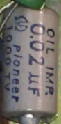
Also, apart from the electrolytics, the other components seem to be a departure from the normal wax covered capacitors and carbon resistors found in similar vintage amplifiers. The capacitors are marked 'Oil Imp.', presumably oil impregnated. Is there anything that should be replaced as a matter of course, before I try to poer it up?


.jpg")
The supply voltage is 100V or 117V. The output tubes are 6AR5 in push pull, and max power is 15W from both chanels.
I have seen a 100W supply for 110V for sale, and was wondering if that would be enough for a supply, so I can run it with its existing transformer. Unfortunately I can't find too much data about this amplifier, so I do not have a supply power rating for it. Would it be pushing it a bit to much to use a simple 100W adaptor for the supply?
Also, apart from the electrolytics, the other components seem to be a departure from the normal wax covered capacitors and carbon resistors found in similar vintage amplifiers. The capacitors are marked 'Oil Imp.', presumably oil impregnated. Is there anything that should be replaced as a matter of course, before I try to poer it up?
Attachments
Last edited:

I think it will work. My calculations:
Filament power
6 x 12AX7 = 6,3 V x 1,8 A = 11,34 W
4 x 6AR5 = 6,3 V x 1,6 A = 10,08 W
2 x 5R-K16 = 5 V x 2,4 A = 12 W
Anode and screen power
2 x (2 x 6AR5) pp:
Va = 285 V
Vg2 = 275 V
Ia = 4 x 27,5 (30,5) = 110 (122) mA so P = 285 x 110 (122) = 31,35 (34,77) W
Ig2 = 4 x 4,5 (6,5) mA = 18 (26) mA so P = 275 x 18 (26) = 4,95 (7,15) W
6 x 12AX7 = ca. 10 mA
Va average = 100 V
P = ca. 1 W
Ptot secondary = ca. 70,7 (76,3) Watt
Ptot primary (adding 10 % for losses in the power transformer) = ca. 77 (84) Watt
Note: The numbers between brackets represent currents/powers at maximum power (which in practice will seldom be reached with music/speech)
Edit: You have to add about 4 watts which are being dissipated in several resistors, but the total will still stay safely below 100 Watt.
Last edited:
Nice!
That should be fun to restore (and if desired, to modify after the restoration).
The chassis looks like steel.
The Design Center of the 6AR5 is:
250V Plate
250V Screen
8 Watts Plate
2.5 Watts Screen
The amp likely is exceeding the design centers, runs a little hot, but it might not reach the maximum specs.
For any Newbees reading this thread:
"Never modify an amplifier until 'after' it is put in good working condition".
Last edited:
Do not purchase a new power transformer.
Instead, purchase a 6.3V, or 12.6V transformer as needed to use as a "Buck" Transformer.
Wire the 6.3V or 12.6V Primary across your power mains.
Then wire the 6.3V or 12.6V transformer Secondary in series with the original power transformer Primary.
With the correct phase connections, you will Buck your power mains voltage to be the voltage that the Pioneer original power transformer needs.
Example:
Suppose your power mains are 120V.
120V - 6.3V = 113.7V
Or . . .
120V - 12.6V = 107.4V
More to consider:
If the Pioneer amp is rated to take 2 Amps from the power line,
Then the 6.3V or 12.6V Buck transformer only needs to be a 2 Amp secondary.
The transformer may even be small enough to fit somewhere on the amp chassis (not likely on your crowded chassis).
Just build a small metal box, put an IEC in socket on it to take power from the Mains, wire the amp power cord to the box in the correct phase, and put the transformer in the box, with the proper phase. It will Buck, not Boost then.
That way, the phase will always be correct to keep it in the "Buck" connection.
Last edited:
Do not purchase a new power transformer.
Instead, purchase a 6.3V, or 12.6V transformer as needed to use as a "Buck" Transformer.
Wire the 6.3V or 12.6V Primary across your power mains.
Then wire the 6.3V or 12.6V transformer Secondary in series with the original power transformer Primary.
With the correct phase connections, you will Buck your power mains voltage to be the voltage that the Pioneer original power transformer needs.
Example:
Suppose your power mains are 120V.
120V - 6.3V = 113.7V
Or . . .
120V - 12.6V = 107.4V
More to consider:
If the Pioneer amp is rated to take 2 Amps from the power line,
Then the 6.3V or 12.6V Buck transformer only needs to be a 2 Amp secondary.
The transformer may even be small enough to fit somewhere on the amp chassis (not likely on your crowded chassis).
Just build a small metal box, put an IEC in socket on it to take power from the Mains, wire the amp power cord to the box in the correct phase, and put the transformer in the box, with the proper phase. It will Buck, not Boost then.
That way, the phase will always be correct to keep it in the "Buck" connection.
Unfortunately, that simple solution is inapplicable. Sweden is a 50 Hz./"240" V. zone. The OP needs a step down autotransformer, with sufficient current handling capability.
North America, with its 60 Hz./"120" V. power, is the "oddball".
Thanks everyone! I think I’ll all aim to see if I can slowly bring it up to 110v on the variac , to give the electrolytics a chance to reform, keeping an eye on voltages.
The main issue is that there are a lot of bells and whistles that aren’t as important these days, that add up to sources of noise and distortion, for instance the modes (stereo, mono), loudness, the elaborate balance control, etc.
It has Philips style speaker connectors, implying 800ohm output alongside standard speaker impedances. Has anyone ever seen a source of plugs for those sockets?
It has Philips style speaker connectors, implying 800ohm output alongside standard speaker impedances.
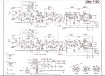
CAUTION! I read the supplied schematic as showing direct connection to the primary side of the O/P "iron".
I also see 100% AC heating. If you plan on using the low level magnetic preamp section, install Sovtek 12AX7LPS or other 7025 equivalents in those sockets.
Those Philips style speaker connectors for 800 (or 400) Ohm speakers have three poles. I never saw one with four poles.
In the schematic of your amplifier I see four poles (the 2 anodes, B+, and ground). Maybe an output for electrostatic loudspeakers?
Yes, I see that now, thanks for highlighting it. That 'B' connector looks like it introduces some feedback that would not normally be connected. I have seen that Pioneer was at the forefront of electrostatic headphones at the start of the 70's, maybe that could be the purpose. Stax had the SR-1 in 1960 which has a similar plug but with 6 pins.
Now I have to track down a user manual!
Cheers, Richard
Highlighting this thread again. Winter is on the way, and I think I will make this my winter project. As mentioned above, it has a lot more controls than are probably needed with modern sources. Plus it has that odd connector that exposes the connections of the primary of the OPT.
6A3Summer made the point that it should be made to work first, then modified, But, I am a bit torn which way to go. The case is a bit damaged, and the knobs are a bit cheap looking - I don't think it is going to command Dynaco SCA35 like prices when it is renovated. However, it has nice output transformers, albeit no UL tap, Would it be more rewarding to simpilfy the schematic, and concentrate on a line level input and frequency response? I think I would like to defeat some of the circuit anyway - have a straight through mode without balance or tone controls.
Interested in the views of others!
I'm looking forward to trying the Phono input - should it perform OK?
Last edited:
At long last got started on this. One advantage of the cold and dark days is that there is a natural break from jobs on the house, so can tinker without guilt ;-)
I tried to slowly crank the amp up to voltage on a variac so I could take voltages from the valve socket pins, but some test music sounded absolutely awful, and I soon saw that it looked like there was DC on the grids of the output tubes, so decided the recap had to be done.
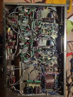
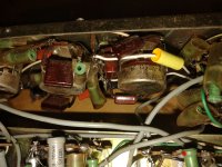
Replaced all the paper in oil (PIO) caps and electrolytics, disconnecting the can caps and fitting new electrolytics under the chassis. It is a metal chassis with AC heaters, so as Eli mentioned above I will probably never have top notch sound. There is an interesting grounding scheme, however, with quite a lot of shielded cables to and from the controls, and a star ground at each input tube, so has had some thought. I left all the resistors after testing a few and they appeared to be within tolerance.
I tested the tubes and they are not perfect but would all classify as 'OK' on a tester. The 6AR5 output tues were around 90%, and the 12AX7s 60%, but well matched halves.
I had some problems getting it powered up again after the recap. The gain/splitter 12AX7 would not conduct on one half, but it looks like that must have been dodgy sockets since eventually after swapping tubes around they all worked OK. Hoping the sockets are just intermittent through lack of use, but they are paxolin and maybe ought to be replaced eventually.
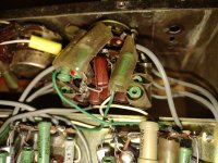
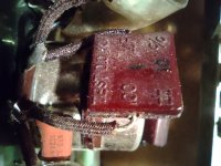
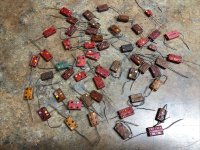
When it was powered up OK I managed to collect all the voltages I needed, and they looked in the ballpark. The volume control is incredibly scratchy in a way that sounds like bad coupling capacitors, so now I need to turn my attention to the non PIO caps. I have attached some pictures and would be greatful for any views on them. Are they a known weakness? The brand is 'Clover' but nothing showed up on Google.
In the end I left it running with some music on the Bluetooth to Aux, and it did not sound too bad.
Now I have to decide the next steps. It is not in such good condition that it has to stay original. There is a switch for 'Stereo, Mono, Channel', where channel is just one channel. I am thinking that I will adapt that so that it can bypass the other controls. That will get me to the point where I can assess how much noise is being contributed from the preamp stage.
There are some electrical safety changes required - exposed fuse at the rear, electrical outputs (which caused melted wires inside), maybe the electrostatic outputs which I can't imagine being needed. That simplifies the wiring a bit.
There are also equalisations not needed at the input, so if I do look at replacing components in the phono section, I will not bother with the Xtal cartridge and Tape head equalisations. Instead add one more line level Aux input.
Anyone with any experience of these amplifiers? The output transformers look OK, 60mm x 70mm so around Dynaco EL84 PP size. It is not impossible they are produced by Tango.
The rectifier tubes are a rarity, 5R-K16. A bit like an EZ81 but with a 5V heater. Thankfully they tested OK.
Thinking where to go with this!
I tried to slowly crank the amp up to voltage on a variac so I could take voltages from the valve socket pins, but some test music sounded absolutely awful, and I soon saw that it looked like there was DC on the grids of the output tubes, so decided the recap had to be done.
Replaced all the paper in oil (PIO) caps and electrolytics, disconnecting the can caps and fitting new electrolytics under the chassis. It is a metal chassis with AC heaters, so as Eli mentioned above I will probably never have top notch sound. There is an interesting grounding scheme, however, with quite a lot of shielded cables to and from the controls, and a star ground at each input tube, so has had some thought. I left all the resistors after testing a few and they appeared to be within tolerance.
I tested the tubes and they are not perfect but would all classify as 'OK' on a tester. The 6AR5 output tues were around 90%, and the 12AX7s 60%, but well matched halves.
I had some problems getting it powered up again after the recap. The gain/splitter 12AX7 would not conduct on one half, but it looks like that must have been dodgy sockets since eventually after swapping tubes around they all worked OK. Hoping the sockets are just intermittent through lack of use, but they are paxolin and maybe ought to be replaced eventually.
When it was powered up OK I managed to collect all the voltages I needed, and they looked in the ballpark. The volume control is incredibly scratchy in a way that sounds like bad coupling capacitors, so now I need to turn my attention to the non PIO caps. I have attached some pictures and would be greatful for any views on them. Are they a known weakness? The brand is 'Clover' but nothing showed up on Google.
In the end I left it running with some music on the Bluetooth to Aux, and it did not sound too bad.
Now I have to decide the next steps. It is not in such good condition that it has to stay original. There is a switch for 'Stereo, Mono, Channel', where channel is just one channel. I am thinking that I will adapt that so that it can bypass the other controls. That will get me to the point where I can assess how much noise is being contributed from the preamp stage.
There are some electrical safety changes required - exposed fuse at the rear, electrical outputs (which caused melted wires inside), maybe the electrostatic outputs which I can't imagine being needed. That simplifies the wiring a bit.
There are also equalisations not needed at the input, so if I do look at replacing components in the phono section, I will not bother with the Xtal cartridge and Tape head equalisations. Instead add one more line level Aux input.
Anyone with any experience of these amplifiers? The output transformers look OK, 60mm x 70mm so around Dynaco EL84 PP size. It is not impossible they are produced by Tango.
The rectifier tubes are a rarity, 5R-K16. A bit like an EZ81 but with a 5V heater. Thankfully they tested OK.
Thinking where to go with this!
Attachments
Leave it alone.
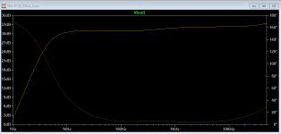
There are multiple high-cut phase-shifts in a tube amp. If they happen at similar Hz it will oscillate. A lag network makes one dominant. This is not the same as a Zobel but if that makes sense to you, OK. The measurements and calculations are very tedious; values are usually determined on the test bench with multiple test loads. It has no effect over most of the audio band, at least the part where the power is. The overall NFB masks the shelf in forward gain.
There are multiple high-cut phase-shifts in a tube amp. If they happen at similar Hz it will oscillate. A lag network makes one dominant. This is not the same as a Zobel but if that makes sense to you, OK. The measurements and calculations are very tedious; values are usually determined on the test bench with multiple test loads. It has no effect over most of the audio band, at least the part where the power is. The overall NFB masks the shelf in forward gain.
I am in a bit of an impasse. I don't feel there is a magic bullet that will return this amplifier to HiFi status, and now I need to get some conviction for what the next steps should be.
Looking at the different stages in the amplifier, are there any thoughts on this RIAA implementation? I have decided that I will rework the input selector. I do not need Tape and Xtal inputs, so I am aiming for 1 Phono input, with RIAA equalisation, and then 3 line level inputs. If I am doing a bit of surgery there, then maybe I can improve the RIAA implementation at the same time.
Also, I am a bit hampered by not having a capacitor tester. There are lot of brown lozenge capcitors (some with brand name Clover) in the input stages and used in the RIAA. If I am going to rework the RIAA implementation, then I would probably build with new components - I have a good selection of silver mica capacitors - and perhaps base on the RCA RIAA implementation.
Attachments
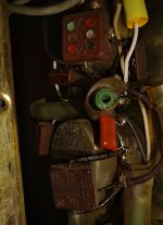
The brown caps you are asking about are look like old mica capacitors. They should have 6 colored circles on 1 side (2 rows of 3) indicating valueAlso, I am a bit hampered by not having a capacitor tester. There are lot of brown lozenge capcitors (some with brand name Clover) in the input stages and used in the RIAA.
View attachment 1127706
Attachments
Was it ever real Hi-Fi? I think Pioneer's best days were still ahead of them. This one has gain of over 1,000 from volume pot wiper to speaker, so sensitivity at wiper is like 13mV, which suggests quite large hiss at idle. The 50K on XTAL and 30K at V1A grid are well off from agreed values. I don't find P-P data for 6AR5 but looks like 8 or 10 Watts which, unless you have large theater speakers, won't do forte well. I think this is a pleasant little home music player. Yes I have lipsticked pigs, and I know good pigs are harder to find every day.return this amplifier to HiFi status
Yes, some do, so those hopefully are rugged. There are some similar style with hand written values.The brown caps you are asking about are look like old mica capacitors. They should have 6 colored circles on 1 side (2 rows of 3) indicating value
I have an ltspice simulation of the amp now, since I am considering some changes. I also was surprised the volume control was where it was. The 0.5v line in signal is down to mV after the tone controls.Was it ever real Hi-Fi? I think Pioneer's best days were still ahead of them. This one has gain of over 1,000 from volume pot wiper to speaker, so sensitivity at wiper is like 13mV, which suggests quite large hiss at idle. The 50K on XTAL and 30K at V1A grid are well off from agreed values. I don't find P-P data for 6AR5 but looks like 8 or 10 Watts which, unless you have large theater speakers, won't do forte well. I think this is a pleasant little home music player. Yes I have lipsticked pigs, and I know good pigs are harder to find every day.
The 6AR5 is the same data as a 6K6GT, and there are curves and operating points for that tube in PP with 285V on the plate and shared cathode resistor if 400R. The OPTs are 12K, so not so flexible.
I took out the tube before the balance pot, so listened to the driver, splitter and output section, and it was totally silent, so I am coming round to the thinking to get it running without the previous stages and adapt the previous 2 stages to an active Baxendall tone control, and a RCA style phono stage. The rectifier tubes are 5V heaters, so maybe further down the line lose them and add a voltage doubler off that tap for preamp DC heaters.
I was looking at the Dynaco SCA35, for some inspiration, but I don't think I would be able to reuse the components I have. The pots in the pioneer are all 500K and branded Noble and probably worth hanging on to.
Adapting the Stereo/mono/channel switch so one option is 'direct' skipping the previous stages, will be the first change and is not too destructive. That will impact the tone stack if I aim to keep the volume control.
Last edited:
re: post #16: Of course you'll want to remove the low level switching and change R9||R7 to standard loading 47K. The single 12AX7 phono equailzer is (or at least was, before simulations) a wonderfully challenging puzzle, and very often encountered when restoring Golden Age gear. Yours looks like a very clean design, but I'd worry about having enough open loop gain for very low frequencies - R10 is the correct value for lots and lots of open loop gain, but may be too small for here. This page:
https://www.audioregenesis.com/
and download the PDF at PAS Phono Stage has an excellent overview.
How original do you need to keep this guy? If you can bring yourself to leave some (lots) of the front panel knobs not-working, could you live with a rat rodded input selector switch - volume control - output amplifier? I guess it could always be returned back to original later if needed.
All good fortune,
Chris
- Home
- Amplifiers
- Tubes / Valves
- Pioneer SM-R150