Gerrit,
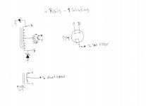
What topology did you employ in the B+ PSU? If you used FWCT, it's easy enough to convert to a dual rail, "tall" low current and "short" high current, setup. A "tall" rail allows large valued 12AX7/ECC83 plate load resistors to be employed. Large valued load resistances keep stage gain up.
What topology did you employ in the B+ PSU? If you used FWCT, it's easy enough to convert to a dual rail, "tall" low current and "short" high current, setup. A "tall" rail allows large valued 12AX7/ECC83 plate load resistors to be employed. Large valued load resistances keep stage gain up.
Attachments
Suppose the two drive levels to the output tubes control grids are not the same amplitudes.
Then the 2nd harmonic of those drive signals, if any, will Not cancel in the output tubes (unless the output tubes also have unmatched gain in the opposite amplitude sense as the drive signals).
Example of where the unequal drive amplitude signals can cancel:
push drive signal +1dB more gain, and push output tube -1 dB less gain;
versus the pull drive signal 0dB, and pull output tube 0dB (signal and gain relative to push).
There is not much chance of it working out that way, but if it does . . .
Then I am going to Las Vegas, and I am going to get real rich.
But again, global negative feedback covers this defect up (real well, so that you may not be able to hear the difference anyway).
Now consider a series phase splitter.
The first tube has 2nd harmonic distortion. It feeds a voltage divider that drives the second stage of the phase splitter.
But the second stage of that phase splitter has its own 2nd harmonic distortion in the opposite direction as the first stage. That means there is a cancellation of the 2nd harmonic distortion when it comes out of the second stage.
Now, we have one output tube driven by a signal that has 2nd harmonic distortion,
and the other output tube is driven by a signal that does Not have 2nd harmonic distortion.
If the output stage is perfectly balanced, that means there is un-cancelled 2nd harmonic distortion coming out of the push pull output stage.
But again, global negative feedback covers this defect up (real well, so that you may not be able to hear the difference anyway).
A cathode coupled phase splitter that has a true current source in the cathodes, and that has identical plate loads (plate resistors, and grid resistors of the next stage), causes intrinsic cancellation of the 2nd harmonic distortion (How about that?).
When testing circuits, or testing parts, and looking / listening for a difference between them . .
you might just remove all negative feedback that could cover up those differences or defects.
Your mileage may vary.
Just my opinion.
Last edited:
Gerrit,
What topology did you employ in the B+ PSU? If you used FWCT, it's easy enough to convert to a dual rail, "tall" low current and "short" high current, setup. A "tall" rail allows large valued 12AX7/ECC83 plate load resistors to be employed. Large valued load resistances keep stage gain up.
Err don't zeners conduct in reverse as diodes.
Last edited:
Err don't zeners conduct in reverse as diodes.
The "hen scratches" are of "S" for Schottky, not "Z" for Zener.
") You could use good quality PN junction diodes, but even the very best of them generate some switching noise. Schottkys are "noiseless".
You could use good quality PN junction diodes, but even the very best of them generate some switching noise. Schottkys are "noiseless".The sample showed vacuum rectifiers, but the configuration works using 100% SS parts too. The "tall" rail is full wave bridge rectified and the "short" rail is full wave CT rectified.
Filter as you see fit. FWIW, I'm partial to choke I/P filtered low current "tall" rails. Sourcing a suitable 20 H. inductor for that job is not especially difficult and the critical current needed for decent regulation is low.
Lots of replies, thank you for that. However I’m still stuck.
Goatguy: I checked all resistors again (for the n’th time…) Values are correct and measure correct. I cannot get symetry, even with (very) low input (below 1 VRMS). Both tube sections draw approx. 4 mA each.
Baudoin0: I have 400 VDC for the 6SN7 stages. Regulated and stable. I also have a negative rail of -50 VDC @ 50 mA. This rail is not used for the final tubes, they have their own (higher) negative supply.
Measurements are done at the phase splitter itself. The output tubes are not connected and the phase splitter is measured across 100KOhm resistors placed after the output capacitor.
stocktrader200: I’ve not been able to find any DN2450, they are very scarce here. I do have 10M45S and 10M90S available. Using these with connection to ground or to a negative rail makes no difference.
Eli: I do have a stable negative rail available, so this can be tried next week when I continue my searching and testing.
6A3sUMMER: I don’t have any global negative feedback when testing, so I can test each stage as it is.
as_audio: I built it without an emitter resistor. What value do you suggest? I presume not a very high value?
Regards, Gerrit
Last edited:

Goatguy: I checked all resistors again (for the n’th time…) Values are correct and measure correct. I cannot get symetry, even with (very) low input (below 1 VRMS). Both tube sections draw approx. 4 mA each.
Ah, well.
You have received a lot of advice so far, yet the problem remains. I always feel bad in asking people to spend money, but I think you're on that edge now.
If you do not have access to a small, cheap, dual-channel (or more) oscilloscope, then please consider buying one. They've become remarkably inexpensive, and do an excellent job in diagnosing just this kind of problem.
Tektronix 2445 oscilloscope, four-channel, 150MHz, TESTED; WORKING | eBay
That there is an exact replica of the one I once owned and loved. Indespensible instrument.
Make sure yours has probes! They can be expensive for same-name-brand ones, if not included.
Moreover, they're FUN.
⋅-=≡ GoatGuy ✓ ≡=-⋅
I have a Velleman PCSGU250 dual channel oscilloscope / signal generator, good enough for audio (up to 12 Mhz). I can easily compare both channels, invert channel 2, etc..
I have built all sorts of (tube) amplifiers before and I cannot find my current problem. What RMS output could I expect from the 6SN7 Aikido stage? I don’t trust anything right now...
More news next week when I continue building / testing.
Regards, Gerrit
I have built all sorts of (tube) amplifiers before and I cannot find my current problem. What RMS output could I expect from the 6SN7 Aikido stage? I don’t trust anything right now...
More news next week when I continue building / testing.
Regards, Gerrit
I have built all sorts of (tube) amplifiers before and I cannot find my current problem.
You've probably successfully built many phase splitters before, could you go back and test one of them to see if it's something to do with your current setup?
This particular application is nothing unusual, you have plenty of voltage to play with, a negative rail, and 25V rms is not that much to swing. Particularly concerning that you measured such a huge difference in the anode voltages for Ketje's schematic which is a pretty standard LTP.
Maybe post a few photos of the actual circuit, along with DC voltage measurements. Maybe somebody will see what you can't
I was going to say you have a bad socket with too much leakage but since you tried an ECC83 as well I assume you used a 9 pin socket instead of an adapter so that would reduce the likelyhood of that. Tubes that are gassy or have too much heater-cathode leakage could also cause an LTP to go out of balance. These tubes would work just fine in a regular common cathode circuit and would test OK on a tube tester.
I believe that too low B+ for the splitter stage is limiting the undistorted output signal level. A general rule of thumb for B+ is not less than 10% of peak output voltage. That is, for 35 VRMS output, B+ should be at least 500 V. If one is looking for really low distortion, the ratio should be 5%.
Transformer phase splitting recommended earlier in this thread virtually doubles B+, thus lowering distortion.
Transformer phase splitting recommended earlier in this thread virtually doubles B+, thus lowering distortion.
- Status
- This old topic is closed. If you want to reopen this topic, contact a moderator using the "Report Post" button.
- Home
- Amplifiers
- Tubes / Valves
- Challenge with Phase Splitter