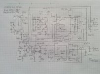
Is Dynaco ST-70 has most modify version tube amp in the history? I had build a auto bias version with output power up to more than 55 watt per channel. The idle bias current can set down to 15 ma if you want without crossover distortion
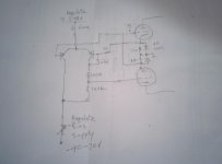
I used solid state rectifier, no choke,but with big filter capacitor, the B+ over 500 Volt at idle. If both channel output at full power the B+ will drop to around 430V. So I add regulate to driver section at 425V. The bias used regulate circuit for idle current setting and ungulate for tubes balance and L/R channel balance.
I used solid state rectifier, no choke,but with big filter capacitor, the B+ over 500 Volt at idle. If both channel output at full power the B+ will drop to around 430V. So I add regulate to driver section at 425V. The bias used regulate circuit for idle current setting and ungulate for tubes balance and L/R channel balance.
Attachments
Solid state rectifier plus an 1800uF input cap, on the original ST70 power transformer . . .
Equals a Very Hot Transformer, Right?
Either have a Carbon Dioxide Fire Extinguisher in the room;
Or be very near to the local Fire Department,
Or, at the very least, be ready to order a power transformer replacement.
Equals a Very Hot Transformer, Right?
Either have a Carbon Dioxide Fire Extinguisher in the room;
Or be very near to the local Fire Department,
Or, at the very least, be ready to order a power transformer replacement.
Last edited:
Umm interesting. I would be concerned over some of the signal getting back through the auto bias at LF unless you make the cathode caps very big. I think would split the emitter resistor and put a cap to ground there instead. Bet the lights dim when you switch that on maybe soft start HT relay.
Last edited:
Maybe that's OK I would check on a simulator. Its about 2.6Hz and there's a lot of gain in the PNP. I think I would expect it to add distortion at 20-50Hz. I may be worth adding a soft HT start - I think you may pop a winding on the transformer after turning it on one too many times which would be a shame.
Last edited:
20mA. I did not know that was your standing quiescent current.
I have a push pull mono-block amp I designed with KT77s that use 24mA each, pretty close.
20mA x 4 x 1.8 (I-squared x DCR factor) makes the current heating of the B+ secondary about the same as a 144mA pure resistive load.
The original ST70 B+ had the intrinsic resistance of the 5AR4 and the low capacitance of the first capacitor. The I-squared peaks were probably not that much more than the new circuit with solid state rectifiers, and very large capacitance first capacitor filter.
How hot does the power transformer get?
I use solid state rectifiers on that power transformer, but I use a Choke input filter, because I do not need such a high B+ voltage.
Err am I reading this right. If the cathode goes more positive then the PNP will conduct more. The collector will go more positive making the grid voltage go more positive. That's not right or am I missing something. If was doing servo bias then I would have a long tailed PNP there with the cathode going into the base.
Last edited:

Yep one set for each tube. I know you want to work out values yourself. I can recommend LTspice simulator. I would go bigger with the filter maybe 2u2 and 22k. The PNP who's collector goes to the -ve just needs a reference voltage of .3v on it. The idea is that when the average cathode voltage is .3v then the bias is correct.
Last edited:
Yep completely separate. So the idea is that the long tailed pair compares the two base voltages a fixed vref of .3 volts and the cathode voltage. The cap integrates the signal over time to remove the audio component. The diode clips the cathode voltage at .65v which helps a lot when the stage enters class B mode. The resistors are set to give the desired bias operating range. You want to make sure it cannot generate anything too small so the tubes don't get hard on. Note at power up the cap will not be charged. I was trying to do something around your existing design. So current = .3/cathode resistor.
- Status
- This old topic is closed. If you want to reopen this topic, contact a moderator using the "Report Post" button.
- Home
- Amplifiers
- Tubes / Valves
- Dynaco ST-70 Auto Bias version