I designed and built this amplifier.
Quite a while ago, I mentioned it to one of the members of this Forum.
He was interested in seeing the schematic.
I apologize to him, it took me so long to document it on this forum.
I am not a software geek.
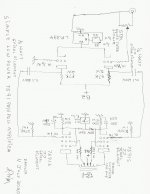
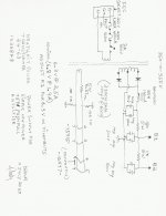
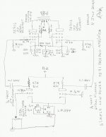
You will have to print the schematics out if you want them.
Then you can rotate them so that they are easier to read.
Warning / Caution: This amplifier has Dangerous Voltages, both at the Mains Power side, and at the B+, tube plates, tube screens, and output transformer primary, etc.
Changing parts for different ones may cause fire, etc.
All building, using, and modifications are at your own risk.
I am not responsible for your actions.
If you see an error in my schematics, please let me know; ask a question, etc.
I am subject to making human errors.
Quite a while ago, I mentioned it to one of the members of this Forum.
He was interested in seeing the schematic.
I apologize to him, it took me so long to document it on this forum.
I am not a software geek.
You will have to print the schematics out if you want them.
Then you can rotate them so that they are easier to read.
Warning / Caution: This amplifier has Dangerous Voltages, both at the Mains Power side, and at the B+, tube plates, tube screens, and output transformer primary, etc.
Changing parts for different ones may cause fire, etc.
All building, using, and modifications are at your own risk.
I am not responsible for your actions.
If you see an error in my schematics, please let me know; ask a question, etc.
I am subject to making human errors.
Attachments
Last edited:

That's a really nice little monoblock.
Could you give us a little info on the Edcor custom 10k p-p OPT you used? CXPP25 series? Higher wattage? Lower?
Could you give us a little info on the Edcor custom 10k p-p OPT you used? CXPP25 series? Higher wattage? Lower?
rongon,
Thanks!
And thanks for asking.
I got the transformer from a fellow vacuum tube club member.
It might have been a custom built, or it may have been a standard model.
The CXPP10-MS-10K is probably what it is.
10 Watt, 10k p-p, with 4 and 8 Ohm outputs. That model has 40% UL taps.
I am certain the one I have is 10 Watt, 10k p-p, and 4 and 8 Ohm outputs.
But I do not remember what I measured the UL tap percentage to be.
I will have to measure it again, and then let you know.
rongon,
I measured my Edcor OPT:
The UL taps are exactly at 40%.
As to size:
The laminations are 1 inch stack, 2 1/2 inch wide, and 3 inch tall.
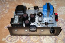
The amplifier weighs 13.2 lbs.
Just like all the amplifiers I make, it has a metal Drawer Handle to make it easy to move from room to room. You can see the handle on the back in the picture I posted.
I measured my Edcor OPT:
The UL taps are exactly at 40%.
As to size:
The laminations are 1 inch stack, 2 1/2 inch wide, and 3 inch tall.
The amplifier weighs 13.2 lbs.
Just like all the amplifiers I make, it has a metal Drawer Handle to make it easy to move from room to room. You can see the handle on the back in the picture I posted.
I believe it is an indicative representation of a current measurement point.
Initially I assumed cathode current, but it appears to be to measure Suppressor grid current.
I'm not entirely sure why you would want or need to measure G3 current/current balance.
There may be a very good reason, especially in PP output stage, but I have exactly zero experience of PP, so I can only guess hehe.
Maybe the OP can explain?
Last edited:
It looks like the meter is measuring combined cathode current for both tubes--g3 is connected to cathode on both tubes.
Got it being dumb - cheers! Sometimes you look at things expecting the meter to be differential when its not.
Last edited:
I wanted to monitor the total cathode current (plus hopefully very low Beam Former currents) of both output tubes.
I already did Individual tube measurements when I bench tested the amplifier.
(I am very careful to make sure the currents in the OPT are very well balanced).
A simple switch and two 25k resistors would have allowed individual measurement.
But it would have violated my idea of making this a Simple Amplifier, including easily looking at the total current from across the room (no button pushing/switching required).
If there are any changes in one or both tubes, I will easily see it.
When I had a job that took me to Thailand, I used to watch the DC current meters on all the transmitters, with RF power levels of 1,000, 3,000, 10,000 and 45,000 watts.
At least 2X a day I would walk in front of each transmitter, and check the current.
"Identical" models did not read identical, but I "knew" each transmitter, and if it was starting to go soft, or to draw more current.
I knew if those readings did not change, they were still operating well and properly.
The photo of my 7591 amplifier was taken with the amplifier un-powered.
If the needle was reading upscale, I would have known that the amplifier had a problem. Ha Ha
Note: I gave up drawing "glass" envelopes around tube symbols decades ago.
The 7591 does not have a Suppressor Grid. And I gave up drawing Beam Formers decades ago (Sorry, I can see how I caused confusion in my schematic).
The 7591 Beam Formers are Internally connected to the Cathode.
You can not measure the Beam Former current by itself (not unless you open the tube, disconnect the Beam Formers from the cathode, bring the Beam Former connection to an unused header pin, have a glass factory, a special welder, a vacuum pump, and an RF Diathermy heater).
Oh, I forgot you need the proper substance to re-fill the "getter trough").
I do not re-build or modify vacuum tubes. I only build and/or modify amplifiers. Ha Ha
Last edited:
I am attaching a report of the measurement results of the 7591 amplifier I built and described in this thread.
It is not great performance, but it is OK when used as I intended it . . . for low power near field listening at the computer (near field = 2 or 2.5 feet from the ear).
I may get the time later to do more extensive testing, adding 2nd order IM distortion test with mixed low and high frequency tones 4:1 amplitude, and 3rd order IM distortion test with 2 closely spaced frequencies.
I also hope to do another 2nd and 3rd Harmonic distortion test, but this time at 2 or 3 Watts output.
I am attaching an FFT plot of the amplifier with an impulse from the Denon Audio Technical CD.
You can see the quick test of the frequency response that an impulse gives. You can see the rolloff at 22.05kHz, just as expected from a CD.
Of course the spot frequency test results I listed in the other attachment in this post are more definitive and accurate.
Attachments
Last edited:
Nice.
Damping of 1.5 is definitely low, but I'm sure you expected that from a UL output with no NFB applied. Have you listened to it? What kind of speaker is it intended to drive?
I suppose the normal way to finish this up would be to add some NFB, probably global. Were you planning to add some?
Damping of 1.5 is definitely low, but I'm sure you expected that from a UL output with no NFB applied. Have you listened to it? What kind of speaker is it intended to drive?
I suppose the normal way to finish this up would be to add some NFB, probably global. Were you planning to add some?
rongon,
Thanks for reading my post, and thanks for asking!
I fully expected the low damping factor when I designed and built the amp.
I did not want any negative global feedback, negative Schade feedback, etc.
I only wanted to use either Ultra Linear negative feedback, or Triode Wired negative feedback.
I have been listening to that amp for a few years.
Let me say I have been Enjoying listening to that amplifier.
I have used that amplifier on many loudspeakers, Electro Voice 'E-V Two' with closed box 12 inch, and a Horn HF driver, Usher S-520 two-way, Bozak B201A two-way, EPI 100V two-way, Sony ss - u3030 two-way (I replaced the 6.5 inch woofer with another, the old one's foam fell apart),
3 different model numbers of small/medium sized two-way Polk speakers, R20, CS175I, and no model number; and a two-way Teac LS-F401.
I also listened to that amp on a two-way Triad InRoom/Silver/MiniMonitor, but I am mystified, I do not particularly like the sound that speaker on any of my PP or SE amplifiers.
I also listened to 2 different models of two-way speakers of my own design, but did not like the sound of one of those designs (I did not like that one design on any of my amplifiers, it is being parted out for something else).
I only drew the schematic in 2020 because a Tubes / Valves reader heard about my amplifier in another thread, and he wanted details (so I finally got around to doing the schematic one or two years later,and so I started this thread).
Last edited:
That's pretty unconventional, but hey, I believe you! That's a wide variety of speakers. EPI 100? I remember those. That's pretty small, but speakers had higher sensitivity back in those days.
The only UL amp I tried without gNFB was a Dyna ST70 that I rewired to a 6SN7 LTP into push-pull 6L6GCs. I had originally intended to use it triode-wired but gave UL a whirl. The UL wired version sounded too brash to me. I added gNFB and then it sounded like pretty much every other PP tube amp, so I lived with it triode-wired for a while. Then I tried a couple other things which didn't really float my boat, so now it's on a shelf, waiting for the next experiment.
One of these days I'll start on another tube power amp. Maybe PP EL86-triode...
In 1996 when I got back into vacuum tube amplifiers, I purchased a used Dyna ST70.
Listened to it stock.
Removed Negative Feedback, left it UL (damping factor about 1.4), the pentode driver struggled with that, at such low self bias voltage, and no negative feedback to push the cathode voltage up when the 8 Ohm output went positive (lost dynamic range).
Triode wired it, the pentode driver was too wimpy for that.
In that order.
Then I removed the output transformers, separated the Es and Is, and used an air gap,
and one EL34 per channel in single ended, with cathode feedback from the 16 Ohm tap (and the primary was connected out of phase to make the cathode feedback negative).
That story went into "Sound Practices" Issue 10.
I re-opened this thread, because I performed some modifications to the amplifier.
1. Triode Wiring the 7591 using 100 Ohm resistors from plate to screen (the amp is no longer Ultra Linear).
2. I changed the B+ from a strict choke input filter to a "motor start" capacitor input filter (2 uF).
That raises the B+ voltage, and because it is now Triode wired, it increases the plate current. That increases the cathode current which increases the self bias voltage. The gain of triode wiring is lower than Ultra Linear, so a little higher bias voltage gives a little more power output than lower bias and lower B+ can give.
Perhaps I will do some re-measurements; It will have lower power than Ultra Linear, but it will have a little higher damping factor than Ultra Linear.
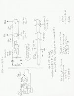
I am attaching rotated schematics, I hope you can read them easier.
Note: I did not change the schematic, the screens now go through 100 Ohm resistors to the plates; they do Not go to the Ultra Linear taps; and I did not draw in the 2uF cap input filter that is right after the rectifiers.
Lately, I have been listening to this amplifier on a ProAc Tablette 2000 Signature T2000S speaker near my computer. It sounds pretty good.
1. Triode Wiring the 7591 using 100 Ohm resistors from plate to screen (the amp is no longer Ultra Linear).
2. I changed the B+ from a strict choke input filter to a "motor start" capacitor input filter (2 uF).
That raises the B+ voltage, and because it is now Triode wired, it increases the plate current. That increases the cathode current which increases the self bias voltage. The gain of triode wiring is lower than Ultra Linear, so a little higher bias voltage gives a little more power output than lower bias and lower B+ can give.
Perhaps I will do some re-measurements; It will have lower power than Ultra Linear, but it will have a little higher damping factor than Ultra Linear.
I am attaching rotated schematics, I hope you can read them easier.
Note: I did not change the schematic, the screens now go through 100 Ohm resistors to the plates; they do Not go to the Ultra Linear taps; and I did not draw in the 2uF cap input filter that is right after the rectifiers.
Lately, I have been listening to this amplifier on a ProAc Tablette 2000 Signature T2000S speaker near my computer. It sounds pretty good.
Attachments
Last edited:
I guess this amp also lends itself to a bit of GNF very easily if you want better damping factor.
Yes, I'm curious... Why not apply 6 to 10dB global NFB to the ultralinear wired version, rather than rewiring the outputs to triode?
Of course, you might just prefer the sound of the amp with the outputs wired triode, which would make sense to me! 👍
Of course, you might just prefer the sound of the amp with the outputs wired triode, which would make sense to me! 👍
- Home
- Amplifiers
- Tubes / Valves
- A Simple Low Power 7591 Push Pull Amplifier