Hi all. I am stuck with a thorny problem and I'm hoping someone out there can help.
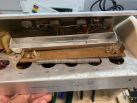
I'm restoring a really early 1968 Silvertone 1422/Sears 40XL combo amp. I've got both channels of the amp up and running and sounding really good (just replaced all the electrolytics and several resistors that were out of spec). However, I was not surprised to find that the reverb was not working. I took the reverb unit apart hoping the problem was just a wire that had come loose. Instead I found a very primitive reverb using a couple of piezoelectric tabs. Apparently this was a common early reverb used on Danelectro amps made for Sears. I've attached a copy of a photo of the disassembled unit. Anyway a tab on one of the piezo units is disconnected at the base and not able to be fixed.
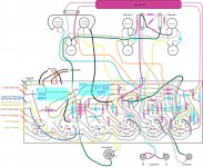
I would like to replace it with an Accutronics or other modern transducer reverb tank, but I don't know if the drive and recovery circuits are up to the task. One of the great frustrations of working on these amps is that there is no schematic available anywhere on the web. So, in order to begin the restoration process I made a detailed layout of the PCB, components and wiring to suss out the power circuit and other amp modules. I've attached a copy of the layout that I did. I don't have the ability to convert this to a schematic, bit I think I have figured out that the reverb drive is the output of one-half of the first 12AX7 (identified as V1 on the layout) coming off the plate (pinout 7) and traveling up to the reverb unit through a simple capacitor coupling. As best I can tell, the return is from the green wire on the center tab of the reverb pot which is connected to the right hand terminal strip and then back to the amp through the volume and tone networks via the red wire that connects to pin 7 of V3 (another 12AX7) through another simple capacitor coupling.
If anyone can help me figure whether a transducer replacement is possible it would be much appreciated.
I'm restoring a really early 1968 Silvertone 1422/Sears 40XL combo amp. I've got both channels of the amp up and running and sounding really good (just replaced all the electrolytics and several resistors that were out of spec). However, I was not surprised to find that the reverb was not working. I took the reverb unit apart hoping the problem was just a wire that had come loose. Instead I found a very primitive reverb using a couple of piezoelectric tabs. Apparently this was a common early reverb used on Danelectro amps made for Sears. I've attached a copy of a photo of the disassembled unit. Anyway a tab on one of the piezo units is disconnected at the base and not able to be fixed.
I would like to replace it with an Accutronics or other modern transducer reverb tank, but I don't know if the drive and recovery circuits are up to the task. One of the great frustrations of working on these amps is that there is no schematic available anywhere on the web. So, in order to begin the restoration process I made a detailed layout of the PCB, components and wiring to suss out the power circuit and other amp modules. I've attached a copy of the layout that I did. I don't have the ability to convert this to a schematic, bit I think I have figured out that the reverb drive is the output of one-half of the first 12AX7 (identified as V1 on the layout) coming off the plate (pinout 7) and traveling up to the reverb unit through a simple capacitor coupling. As best I can tell, the return is from the green wire on the center tab of the reverb pot which is connected to the right hand terminal strip and then back to the amp through the volume and tone networks via the red wire that connects to pin 7 of V3 (another 12AX7) through another simple capacitor coupling.
If anyone can help me figure whether a transducer replacement is possible it would be much appreciated.
Attachments
1) the reverb driver can supply VERY LITTLE current, barely enough for the very high impedance piezo driver, absolutely insufficient for a magnetic Accutronics type one, even the highest impedance one.
You might add an extra socket and 12AT7 (or AX7) and a driver thansformer to install there a Fender type reverb circuit.
Magnetic reverb output signal should be usable with that reverb return circuit, maybe tweaking it a little.
Or attenuate piezo drive signal to drive an Accutronics digital reverb module which sounds fine but requires its own 5V supply.
JM thanks for the response. I was afraid that was the case. I'll have to look into what mods would be necessary to build the required driver stage but I'm not optimistic. The chassis is pretty small and I'm not sure where I could fit in another tube and associated circuitry, although the point where the reverb coupling circuit leaves the board would be the place to insert it electronically. I might just have to wait until one of these reverb units comes up for sale (they do occasionally because they were used in several different Danelectro built amps). Anyway, much thanks for the info.
EVEN IF a piezo reverb tank is offered, it´s very difficult it will work properly or at all (putting it kindly).
There is a Plan B: you can do what 95% of commercial tube amp builders do and cheat a little by having an Op Amp based Reverb circuit.
If you dare ....
You´ll need +/-15V to feed the OpAmp (a small 12VAC transformer is enough, 12+12VAC even better) , a cheap Op Amp, a dozen components and a small perfboard, veroboard or similar to hold it.
No need for a cabinet since you´ll bolt it to the chassis, probably inside.
You´ll need to read a schematic (we must talk the same language") ) and somewhat proficient with your hands (drilling, soldering, etc.) and last but not least , be able to use a multimeter.
) and somewhat proficient with your hands (drilling, soldering, etc.) and last but not least , be able to use a multimeter.
If not, enroll a solder fume head friend, bribe him with whatever he fancies.
This is the basic reverb circuit from Fender Blues Junior, a 15W all tube amp (except reverb of course).
Since you already have a functional Reverb circuit in your amplifier, adding this is easy, it basically behaves like the original tank but is active, instead of passive.
But it takes guitar signal at the input and outputs same delayed a few milliseconds, that´s all the original tank does anyway.
And it will sound WAY better than the original one.
You will need to buy a Belton/Accutronics/Mod tank, of course, and mount it somewhere.
There is a Plan B: you can do what 95% of commercial tube amp builders do and cheat a little by having an Op Amp based Reverb circuit.
If you dare ....
You´ll need +/-15V to feed the OpAmp (a small 12VAC transformer is enough, 12+12VAC even better) , a cheap Op Amp, a dozen components and a small perfboard, veroboard or similar to hold it.
No need for a cabinet since you´ll bolt it to the chassis, probably inside.
You´ll need to read a schematic (we must talk the same language
) and somewhat proficient with your hands (drilling, soldering, etc.) and last but not least , be able to use a multimeter.If not, enroll a solder fume head friend, bribe him with whatever he fancies.
This is the basic reverb circuit from Fender Blues Junior, a 15W all tube amp (except reverb of course).
Since you already have a functional Reverb circuit in your amplifier, adding this is easy, it basically behaves like the original tank but is active, instead of passive.
But it takes guitar signal at the input and outputs same delayed a few milliseconds, that´s all the original tank does anyway.
And it will sound WAY better than the original one.
You will need to buy a Belton/Accutronics/Mod tank, of course, and mount it somewhere.
Attachments
JM - After your earlier message I did some research on reverb drive circuits and came across the same solid state driven circuit on Rob Robinette's website. I think it's a good mod and not too difficult to do. I can and do read schematics, just not conversant enough to create a schematic from the layout that I did. I'm pretty decent with soldering, really familiar with multimeters and used to working around the high voltages in tube amps, so I'm going to give it a try. thanks again.
- Status
- This old topic is closed. If you want to reopen this topic, contact a moderator using the "Report Post" button.