Hey Eli, or whoever might be interested...
Thinking of this amp, the ever-popular "El Cheapo" using PP 12AQ5/6AQ5 (6V6oids) with a 12AT7 LTP driver:
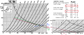
Has anyone made an El Cheapo with PP EL86-triode? That would allow the use of more commonly attainable OPTs with 3k to 5k p-p primary impedance, which wouldn't work so well with 6V6oids. EL86 won't stand as high plate voltages as 6V6, but 275V plate-cathode should be safe for them wired triode. What's the usual resulting B+ from an N77U using a voltage-doubler? I figure about 300V, which would be pretty close to perfect.
Also, I've read many times in many places that it's easier to make a high-performing OPT with a lower stepdown ratio. Perhaps that opens up the door to Edcor iron?
EDCOR - CXPP Series Output Transformers
Those are just Edcor's 25W and 30W offerings. They also have 50W rated OPTs in similar impedances.
What I don't know is what kind of primary inductance they have.
--
Thinking of this amp, the ever-popular "El Cheapo" using PP 12AQ5/6AQ5 (6V6oids) with a 12AT7 LTP driver:
Has anyone made an El Cheapo with PP EL86-triode? That would allow the use of more commonly attainable OPTs with 3k to 5k p-p primary impedance, which wouldn't work so well with 6V6oids. EL86 won't stand as high plate voltages as 6V6, but 275V plate-cathode should be safe for them wired triode. What's the usual resulting B+ from an N77U using a voltage-doubler? I figure about 300V, which would be pretty close to perfect.
Also, I've read many times in many places that it's easier to make a high-performing OPT with a lower stepdown ratio. Perhaps that opens up the door to Edcor iron?
EDCOR - CXPP Series Output Transformers
Those are just Edcor's 25W and 30W offerings. They also have 50W rated OPTs in similar impedances.
What I don't know is what kind of primary inductance they have.
--
Voltage doubling a N-77U gets you a bit more than 300 V. 2.6X the AC mains voltage is a reasonable approximation. Resort to boosting "iron" was needed to get the B+ up to where a 6V6oid is "happy".
For a "6" WPC triode wired 6V6oid "El Cheapo", Edcor's GXPP15-8K should be quite satisfactory. I'm guessing that 0.68 μF. as the high pass cap. value will be safe.
The 'T7 triode sounds very good with an IB of 3 mA. and roughly 210 V. on the plate. To use 275 V. B+ requires reducing the LTP load resistor value and unacceptable loss of gain. You might solve that problem by adding DC coupled ZVN0545A source followers between the LTP and the "finals". Something has to be done to raise the net load impedance "seen" by the 'T7 triodes.
Ah, yes. The driver tube is key, of course.
Thanks for the estimate of B+ from the N-77U. I get about 120VAC mains here. If the N-77U makes +310V rectified, then with cathode bias of something like -30V for the EL86s, that would put their plate-cathode voltage at +280V. It's a 12W tube (actually 12W plate + 2W screen), so 45mA each should be within reason.
If the 12AT7s have 175V on their plates, about -2V grid bias, 3mA plate current each, do you think that would work out well enough?
The reason I'm going here is that I have some Russian 6P43P-E I'd like to use, and I have a pair of 25W-rated 6.6k OPTs as well.
--
I'm thinking a topology other than "El Cheapo" might be "best". Perhaps something along the lines of the near Class "B" 6Y6 amp I worked on with Jeff Yourison could be adapted to your tubes.
Full pentode mode with regulated g2 B+ allows reasonable liberty to be taken with the anode B+ voltage limit. As long as you are relentless in keeping anode dissipation within published limits, things tend to work out well. Heat, not mere volts, is the tube destroyer.
BTW, Antek's AS-1T230 toroidal power trafo looks like a very nice fit for this project.
Attachments
The problem is adequately loading the 'T7 LTP. Roughly 210 V. on the plate and an IB of 3 mA. are in order. The RP of the 'T7 is approx. 15 K. Even with ZVN0545A buffering, the plate load resistors should be 33 K. The voltage drop for 3 mA. in 33 K is 99 V. Things are being cut too fine for my liking. However, it could work out OK.
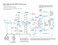
The EL86 can be used with minor changes.
Replacing the choke with a 150Ω resistor (or a choke with same DCresistance) gets the power down to 280V.Minus drop cathode resistor and DCresistance OPT gives 250V on the tube, is the max for a PL84 (=EL86 other heater).
With 275V supply for the ECC81 the anode gets 135V, enough room to give the output tube ±26V.
Only have to find a transformer 6,3V at 4A for the heaters.
Mona
Attachments
If there's 300VDC for the B+ to the 12AT7 LTP, then there should be enough swing to drive the output tubes.
Take note that EL86 as triode has much lower gain than EL84 (as triode).
To drive full, EL86 requires 17 Vrms while EL84 only 7,5 Vrms.
Take note that EL86 as triode has much lower gain than EL84 (as triode).
To drive full, EL86 requires 17 Vrms while EL84 only 7,5 Vrms.
This point pretty well stops things, in their tracks.
 Reduced B+ = reduced net 'T7 anode load impedance and consequent reduced gain.
More and more, voltage amplifier into "concertina" phase splitter looks right for PP EL86 "finals". A nice MOSFET has an advantage over a triode, in the "concertina" phase splitter role, when B+ volts are scarce. The FET can swing closer to the B+ rail than a triode can.
Doesn't the 6CW5 family of output tubes require plate to plate loads in the 3k to 3k5 range, rather than 6k6, when operating as pentodes? Hence, tied as triodes the load impedance should be expected to be even lower?The reason I'm going here is that I have some Russian 6P43P-E I'd like to use, and I have a pair of 25W-rated 6.6k OPTs as well.
--
Best regards!
Well, with triodes in the output stage, using a higher load impedance reduces THD but also reduces output power. Most designs use 2x the triode's rp to get the most power out possible, but that will be at higher THD for a given circuit.
I once built a PP 300B amp using 6.6k output transformers (UTC LS63, which I should have kept!). You couldn't really tell the power output was less, but you sure could hear how clean it was and the nice damping in the bass.
Given the higher-than-usual load impedance, I was hoping to get away with no global NFB loop.
Another possibility might be to use a 12AX7 LTP into ZVN0545 MOSFET source followers, into the EL86s, with 6dB gNFB. What do you think? Would that be a solution? It seems to work on paper...
--
Last edited:
The reason for source followers after a 12AX7 LTP would be to avoid slew limiting into the Miller capacitance of the output triodes' grids. The 12AX7's Ip of 1mA or slightly less would not be enough. I figure a ZVN0545 sourcing 3 to 4mA would do it. Maybe even better would be 5mA+ from FQPF2N60C or something like that (with Crss of 5pF or less).
Any class AB capability would be gravy, but not the goal here.
--
Any class AB capability would be gravy, but not the goal here.
--
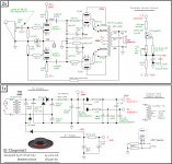
As a reference, this is a version I have tested.
As triode connected:
-Pout = 11.3 W, +Ub = 300 V, OPT = 5k
-Pout = 7.8 W, +Ub = 200 V, OPT = 5k
As UL:
- Pout = 23.5 W, +Ub = 300 V, OPT = 5k
- Pout = 16.8 W, +Ub = 250 V, OPT = 5k
As triode connected:
-Pout = 11.3 W, +Ub = 300 V, OPT = 5k
-Pout = 7.8 W, +Ub = 200 V, OPT = 5k
As UL:
- Pout = 23.5 W, +Ub = 300 V, OPT = 5k
- Pout = 16.8 W, +Ub = 250 V, OPT = 5k
Attachments
Thanks artosalo.
Perhaps 6F12P is the way to go. I have a few, so I guess I could use 'em.
When you wired the amp triode, did you try it without the NFB loop? Does it sound OK that way?
What grid bias voltage do the 6P43P-E output tubes require with the +300V supply?
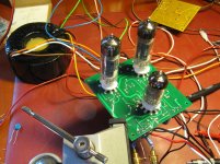
Did you fabricate the circuit board in the photo?
Perhaps 6F12P is the way to go. I have a few, so I guess I could use 'em.
When you wired the amp triode, did you try it without the NFB loop? Does it sound OK that way?
What grid bias voltage do the 6P43P-E output tubes require with the +300V supply?
Did you fabricate the circuit board in the photo?
I have made only measurements, not actual listening tests.
Without GNFB the THD is some 2.0 % just before clipping.
At 300 V +Ub I used Ug1 = -38 V, Ik = 33 mA/tube (idle).
At 250 V +Ub I used Ug1 = -31 V, Ik = 20 mA/tube.
Those values gave best linearity with 5k OPT.
PCB's were done some 10 pcs.
Without GNFB the THD is some 2.0 % just before clipping.
At 300 V +Ub I used Ug1 = -38 V, Ik = 33 mA/tube (idle).
At 250 V +Ub I used Ug1 = -31 V, Ik = 20 mA/tube.
Those values gave best linearity with 5k OPT.
PCB's were done some 10 pcs.
The reason for source followers after a 12AX7 LTP would be to avoid slew limiting into the Miller capacitance of the output triodes' grids. The 12AX7's Ip of 1mA or slightly less would not be enough. I figure a ZVN0545 sourcing 3 to 4mA would do it. Maybe even better would be 5mA+ from FQPF2N60C or something like that (with Crss of 5pF or less). --
Yes, of course you're right. Though Mullard suggested it, 12AX7 isn't that powerful to be used to drive power tubes, at least not in HiFi.
Best regards!
Thanks artosalo.
Perhaps 6F12P is the way to go. I have a few, so I guess I could use 'em.
When you wired the amp triode, did you try it without the NFB loop? Does it sound OK that way?
What grid bias voltage do the 6P43P-E output tubes require with the +300V supply?
Did you fabricate the circuit board in the photo?
Hi rongon,
Have you built your EL86-based El Cheapo, or perhaps artosalo’s schematic, yet? Any feedback on your experience? I have a bunch of good Euro EL86 NOS tubes that I would like to put to use, and wondered about what people experience with regard to max screen voltage/current on these EL86s.
If artosalo is listening, I’m curious if you have any thoughts on why you are able to run your EL86’s in UL mode with almost 300 Vdc across the tubes, while others seem to get screen current runaways at above the datasheet max screen voltage of 200 Vdc. Very high quality Euro NOS tubes perhaps; the higher than most primary output transformer of 5k vs. 3-4k often quoted?
- Status
- This old topic is closed. If you want to reopen this topic, contact a moderator using the "Report Post" button.
- Home
- Amplifiers
- Tubes / Valves
- "El Cheapo" with EL86-triodes?