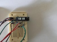
Think I'm going to integrate this little display into my next project to monitor the current for each of the output tubes. It's Arduino based (of course) and plan to add some relays for overcurrent protection. The board will have the sense resistors so you just have to run a wire to each cathode and then one ground. Power will come from a small isolated DC/DC converter so no worries about voltage level issues. Maybe use a few jumpers to set the overcurrent limit.
Now I can already tell that some monocles have fallen from peoples faces at the thought of a microprocessor being near their tube amp
Is there any interest? I don't have a pcb layout yet as I'm still working on the details.
Now I can already tell that some monocles have fallen from peoples faces at the thought of a microprocessor being near their tube amp
Is there any interest? I don't have a pcb layout yet as I'm still working on the details.
Attachments
")
Is there any interest?
I'm interested, but I don't have anything to contribute. My experience to date with Arduino is limited to figuring out how to get my Arduino to speak to my LCD display, and uploading someone else's sketch for a milli-ohm meter (with the author's permission). But very interested in following your project.
I see big potential for using Arduino for monitoring numerous operating conditions - voltage, current, temperature, etc.
cheers, Derek
- Status
- This old topic is closed. If you want to reopen this topic, contact a moderator using the "Report Post" button.
- Home
- Amplifiers
- Tubes / Valves
- Bias monitor display