Though because this is in such a high voltage rail, I'm worried those Hammond chokes wouldn't be up to that task.. It says maximum operating voltage for the 159V is 500VDC, though they're hipot tested to 1500VAC.
You could mount the choke on an insulated plate, and install an insulated cover over it.
I would not use that choke without at least a moderate size input capacitor, though.
You could mount the choke on an insulated plate, and install an insulated cover over it.
I would not use that choke without at least a moderate size input capacitor, though.
It seems as though either I should go all in with a choke input design, which would mean a proper choke for this task, and a new higher voltage power transformer. Or maybe just going for a new power transformer that is more capable of handling the RMS current that my capacitor input power supply is drawing.
Or what I may try first is just sticking with the two 10H chokes I'm currently using and reducing the size of my first capacitor from 10uF to 2uF. I should still be in the voltage range that I want to be, and ripple should still be relatively low.
It would also seem, based on the responses I'm getting on this subject, that putting a resistor between rectifier and first cap in the rail is so laughable it's not even worth discussing.
Last edited:
You can also put the choke in the ground leg.
I suppose that's worth considering, though it's not something I've done before. I'll research that a bit.
It would also seem, based on the responses I'm getting on this subject, that putting a resistor between rectifier and first cap in the rail is so laughable it's not even worth discussing.
My math may be wrong but with 200R added I calculate a current drop of 5ma.
You can also put the choke in the ground leg.
Yes, keep the input capacitor connected directly from the center tap to the rectifier cathodes.
The center tap is no longer grounded. The choke now goes from the center tap to ground.
Last edited:
It seems as though either I should go all in with a choke input design, which would mean a proper choke for this task, and a new higher voltage power transformer. Or maybe just going for a new power transformer that is more capable of handling the RMS current that my capacitor input power supply is drawing.
Or what I may try first is just sticking with the two 10H chokes I'm currently using and reducing the size of my first capacitor from 10uF to 2uF. I should still be in the voltage range that I want to be, and ripple should still be relatively low.
It would also seem, based on the responses I'm getting on this subject, that putting a resistor between rectifier and first cap in the rail is so laughable it's not even worth discussing.
Going back to your original concept...So why not put an additional capacitor in the filter before the R? Like CRCLCLC. Seems like that should be a vast improvement with no detriment to the performance; at least that I can see. It may, electrically speaking, be the same thing as CLCLCRC, which is starting to look pretty mainstream. I've never built an SET, but do you really need two chokes at this point? Maybe CLCRC? If you break up "R" into separate resistors for the purpose of distributing the power dissipation (as discussed above), I would add capacitors between them for added filtering. So now we have CLCRCRC etc...seems I've seen this all the time.
It would also seem, based on the responses I'm getting on this subject, that putting a resistor between rectifier and first cap in the rail is so laughable it's not even worth discussing.
Laughably, maybe even grotesquely, I never implement a capacitor without some series resistance.
It would also seem, based on the responses I'm getting on this subject, that putting a resistor between rectifier and first cap in the rail is so laughable it's not even worth discussing.
IMO depends on the application. Have you confirmed the dynamic current draw of your amp? The SE on my bench sims a supply current draw per channel of 73.311 +_0.015 ma for 1 watt out. The regulation benefits of a choke input may be wasted. While my amp doesn't require your level of voltage drop a resistor input will be used to allow fine tuning of final B+. Guessing the silicon diode rectifiers will also appreciate the resistive load.
..I just wanted to see what others thought about this idea though, and see if anyone has done this before and can comment on it.
.. It will reduce/dampen current charging pulses and can be used with good affect on 'critical' supplies, digital gear for example, I use it (common mode resistor input) for exactly that.
HK
There's ALWAYS a resistor between the AC and the first cap. Winding resistance, diode resistance, and any resistance added to limit peak rectifier current.
I can't see ANY problem (or much good) from another 200r in series with 6,860 ohms.
However you have clearly found a crack in PSUD's logic. With otherwise identical parts it shows 1V MORE with the added resistance; this violates natural law.
Your scaling and excess precision confuses my eye. Added filtering does the same either way you do the rectifier. And "current sources" are fake concepts best avoided. I simplified to get "comparable" plots. (Sadly I overlooked the 930V AC; but the output will scale directly either way.)
Adding the resistor loses 8% of "precious" DC voltage (-0.7dB power) for 14% (-1.2dB) less ripple. A proper engineering job would specify a different transformer if less DC were needed; yes in one-off DIY a lossy dropper may be the only practical hack.
Attachments
There's ALWAYS a resistor between the AC and the first cap. Winding resistance, diode resistance, and any resistance added to limit peak rectifier current.
I can't see ANY problem (or much good) from another 200r in series with 6,860 ohms.
However you have clearly found a crack in PSUD's logic. With otherwise identical parts it shows 1V MORE with the added resistance; this violates natural law.
Your scaling and excess precision confuses my eye. Added filtering does the same either way you do the rectifier. And "current sources" are fake concepts best avoided. I simplified to get "comparable" plots. (Sadly I overlooked the 930V AC; but the output will scale directly either way.)
Adding the resistor loses 8% of "precious" DC voltage (-0.7dB power) for 14% (-1.2dB) less ripple. A proper engineering job would specify a different transformer if less DC were needed; yes in one-off DIY a lossy dropper may be the only practical hack.
Interesting observations. I understand what you're saying for the most part. Though I'm not seeing what you mean by "1V more with added resistance". Where are you seeing 1V more with the added resistance before the first cap?
One thing I did notice with my PSUD2 sims is that for determining the actual load on things once the amp is running it's better to put a bit of reporting delay in like you did.
It just seemed to me like adding that relatively small amount of resistance before the first cap, seemed to reduce current load on the transformer and rectifier by a larger amount than adding that resistance in further down the line.
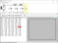
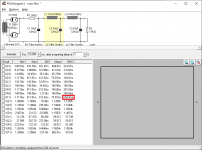
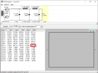
I attached a few images. Using a 7.8K load I have a 230mA RMS load on T1 without that added 200 ohms of resistance, With 200 ohms added before the first capacitor the load is 184mA RMS, and with 200 ohms of additional resistance added after the first capacitor I have 226mA RMS.
So it seems like added resistance before the first capacitor (whether in the secondary winding of the power transformer itself, or with a resistor) reduces the RMS current load on the power transformer more than added resistance after the first capacitor.
If these simulations are accurate, this does seem interesting to me. I understand that from a ripple perspective, there isn't much difference, but from a current load perspective on the transformer and rectifier it seems like where that added resistance is placed creates a pretty big difference.
I don't know, at the very least it seems worth discussing.
Attachments
Last edited:
- Status
- This old topic is closed. If you want to reopen this topic, contact a moderator using the "Report Post" button.
- Home
- Amplifiers
- Tubes / Valves
- Resistor input power supply