Hi,
I have bought two Old unison smart 845
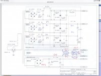
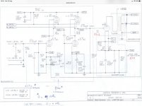
I see that the scheme is quite simple and components not very high-end.
Somebody can tell me which modifications can be applied.
I was thinking to reduce feedback, change coupling condensator, but more than that i cannot do.
I am quite good in electronic DIY, but lack knowledge.
I think that power supply can be well upgraded.
Thanks for help
I have bought two Old unison smart 845
I see that the scheme is quite simple and components not very high-end.
Somebody can tell me which modifications can be applied.
I was thinking to reduce feedback, change coupling condensator, but more than that i cannot do.
I am quite good in electronic DIY, but lack knowledge.
I think that power supply can be well upgraded.
Thanks for help
Feel free to post schematics.Hi,
I have bought two Old unison smart 845
I see that the scheme is quite simple and components not very high-end.
Somebody can tell me which modifications can be applied.
I was thinking to reduce feedback, change coupling condensator, but more than that i cannot do.
I am quite good in electronic DIY, but lack knowledge.
I think that power supply can be well upgraded.
Thanks for help
Modifications
Well first of all components are not so high end, so coupling condensator may well be changed, as output transformer maybe changed with a Tamura or similar.
Also an ecc82 driving an 845 Is not the best choice, maybe there is some replacement with more current.
For me a lower feedback is always a better sound, even if for somebody can result in a less “nice” sound, obviously if scheme and components are not at best a higher feedback help....
Also rectifiers seems to be not as good as it should be...., but if go on with some scheme arrangement.... i do not know.
The amp should sound pretty good as is.
What do you hope to achieve?
Well first of all components are not so high end, so coupling condensator may well be changed, as output transformer maybe changed with a Tamura or similar.
Also an ecc82 driving an 845 Is not the best choice, maybe there is some replacement with more current.
For me a lower feedback is always a better sound, even if for somebody can result in a less “nice” sound, obviously if scheme and components are not at best a higher feedback help....
Also rectifiers seems to be not as good as it should be...., but if go on with some scheme arrangement.... i do not know.
Also an ecc82 driving an 845 Is not the best choice, maybe there is some replacement with more current.
Also rectifiers seems to be not as good as it should be...., but if go on with some scheme arrangement.... i do not know.
12BH7 Or E182CC but its not a plug in replacement in this circuit. If your on a budget 6N6P.
You could add DC heating if there is room in this amp for it.
12BH7 Or E182CC but its not a plug in replacement in this circuit. If your on a budget 6N6P.
You could add DC heating if there is room in this amp for it.
Not direct replacement is not so big problem, i am good in modifications, but need to understand what to do, is only a pin question or need to tune other components?
Luckily there is a lot of room inside the amp, also more condensator can be added ... no problem of space at all.
Is this amp built with point-to-point wiring or a big PC board?
Yes, the ECC82 is an odd choice in that spot. If the circuit is P2P, you could substitute a 6S4A in there with some rewiring.
The 10V DC power supply could be modified to use Schottky diodes and a choke input filter. That would take a bit of the load off of the power transformer.
If these are at all valuable, I would leave them alone. If you open them up and they are using PC board that have no solder mask (they will have that taupe/gray color and silver colored traces), then you really shouldn't mess with them. You may go to put in fancy caps and end up lifting traces on the boards, then you'll be left with a difficult repair.
Is this amp built with point-to-point wiring or a big PC board?
Yes, the ECC82 is an odd choice in that spot. If the circuit is P2P, you could substitute a 6S4A in there with some rewiring.
The 10V DC power supply could be modified to use Schottky diodes and a choke input filter. That would take a bit of the load off of the power transformer.
If these are at all valuable, I would leave them alone. If you open them up and they are using PC board that have no solder mask (they will have that taupe/gray color and silver colored traces), then you really shouldn't mess with them. You may go to put in fancy caps and end up lifting traces on the boards, then you'll be left with a difficult repair.
Thanks for reply,
There are two board, poer and input, and some p2p wiring, not a problem for me on those old plates to do soldering (when i was young i was repairing CPU multilayers board on field around the wordl) surely some attenction must be taken.
Compoments not so good as i told you, standard i can say, nothing that they cared for, bu nice plan where to start.
I was thinking too use hexfred rectifiers.
If i correct understand you suggest to change the two sections of the ecc83 with one triode 6s4, in this case will be better to throw out the input board and remake a P2P input section in single ended configuration changing both the ecc82 and ecc83, maybe there is a reference scheme to use.
The important thing is to use same sockets in order not to compromise the design of the ampli outside.
Another thing that maybe is not useful is the input coupling condenser, what do you think?
Thanks
Last edited:
Schottky diodes will do what? And it would take a sizable input choke to handle the 3.25A filament current.
You have not suggested anything that in my experience produces big positive changes.
Changing caps with a feedback amp? Why? IME no big change.
Reducing designed in feedback will mean more high order distortion and very short listening sessions due to pain.
Changing a driver tube would require major changes and a redesign. You have not suggested that you have that caliber of engineering skills.
If you don't like it and it works, sell it and build your own. The sale will allow you to buy the transformers necessary for a new project. It was an expensive amp at one time was it not?
Richard
You have not suggested anything that in my experience produces big positive changes.
Changing caps with a feedback amp? Why? IME no big change.
Reducing designed in feedback will mean more high order distortion and very short listening sessions due to pain.
Changing a driver tube would require major changes and a redesign. You have not suggested that you have that caliber of engineering skills.
If you don't like it and it works, sell it and build your own. The sale will allow you to buy the transformers necessary for a new project. It was an expensive amp at one time was it not?
Richard
I am able to build almost everyrhing, i did a OTL/OCL with 6C33C P2P wired, my problem is a scheme, or to know which changes to do, i do not have the project skills, i do have the building ones, as well as to use instruments, and repairing skill (lot of old tube radio) i spent about 10 years doing electronic repairing job around the wordl for a tools machine factory.
The first approach is to keep same pin tubes and to do some minor changing.
The second might be to rebuild the input/drive section if possibly keeping the same tube sockets to keep the design of the ampli that is quite enjoiable and in this case make it a SE too.
I can understand that my suggestions are not so conclusive, that is why i am asking for some help.
Here one of the amps i build it was 20 years ago, not very neat job, skills became bette with time, but all with my hands, enclosure, design, Lower frame in aluminium and steel cabinet.
So maybe i can do some modification to the smart 845😉
So maybe i can do some modification to the smart 845😉
- Home
- Amplifiers
- Tubes / Valves
- Unison smart 845 modifications