Hi mctavish; ok so I've switched the A1 and A2 wires... unfortunately it is the same result at power up... silence for ~10-15 seconds, then increasing hum, only this time when I turn the power off, I only get a very faint (barely discernable) level of audio signal at the speaker and the cap discharge time seemed to take a bit longer... I didn't get the high pitched whistle-like sound at the end, this time I got what sounded like a low thump (like a very low note on an electronic organ) or something to that effect.
In your experience though, do you thing that I could (reasonably safely) conclude that before switching the a1 and a2 lines that I had the rest of the build correct? --> given the fact that I had audio signal coming through for a few seconds before the caps dissipated. --> can we isolate this issue to the OT or could there be something else that could cause this?
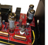
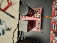
Also: one of the other folks suggested checking orientation of the OT to the mains... (should it be perpendicular to mains?) I don't believe so, here is the link to the amps from the company site showing orientation.
ANK Audiokits - EL34 Triple C-Core Pentode Monoblocks Tube Amplifier
scroll down slightly to the 2nd picture for the level 1 amp... which is the one I'm building.
In your experience though, do you thing that I could (reasonably safely) conclude that before switching the a1 and a2 lines that I had the rest of the build correct? --> given the fact that I had audio signal coming through for a few seconds before the caps dissipated. --> can we isolate this issue to the OT or could there be something else that could cause this?
Also: one of the other folks suggested checking orientation of the OT to the mains... (should it be perpendicular to mains?) I don't believe so, here is the link to the amps from the company site showing orientation.
ANK Audiokits - EL34 Triple C-Core Pentode Monoblocks Tube Amplifier
scroll down slightly to the 2nd picture for the level 1 amp... which is the one I'm building.
Your transformer orientation looks fine.
I've heard the sound you describe many times and in my own experience this kind of trouble is frequently something very simple , so simple that you look at it again and again and because you're sure you've got it right you keep stepping over it in search for a shape shifting elephant.
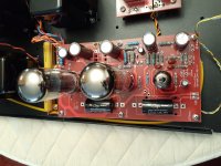
It's often a bad or missing connection, in many cases to ground or chassis ground. All your diodes in the right way ? Where is your circuit grounded to the chassis? and yes better focused pics top and bottom might be useful.
Being A,B,C, . . . . systematic always feels like the long way around but it usually works out to be the least frustrating and leave you with the best understanding. If it were me I'd let out a big sigh and go through every step of the manual making sure I didn't do something like swap the 220Ω and 22KΩ resistors.
Hope this helps some.
I've heard the sound you describe many times and in my own experience this kind of trouble is frequently something very simple , so simple that you look at it again and again and because you're sure you've got it right you keep stepping over it in search for a shape shifting elephant.
It's often a bad or missing connection, in many cases to ground or chassis ground. All your diodes in the right way ? Where is your circuit grounded to the chassis? and yes better focused pics top and bottom might be useful.
Being A,B,C, . . . . systematic always feels like the long way around but it usually works out to be the least frustrating and leave you with the best understanding. If it were me I'd let out a big sigh and go through every step of the manual making sure I didn't do something like swap the 220Ω and 22KΩ resistors.
Hope this helps some.
Are you missing the black wires?
Hey Duke, no I soldered them from the underside... you are referring to the wires for the LED I'm assuming. on mine they are blue/black and red/black for the other amp.
Your transformer orientation looks fine.
I've heard the sound you describe many times and in my own experience this kind of trouble is frequently something very simple , so simple that you look at it again and again and because you're sure you've got it right you keep stepping over it in search for a shape shifting elephant.
It's often a bad or missing connection, in many cases to ground or chassis ground. All your diodes in the right way ? Where is your circuit grounded to the chassis? and yes better focused pics top and bottom might be useful.
Being A,B,C, . . . . systematic always feels like the long way around but it usually works out to be the least frustrating and leave you with the best understanding. If it were me I'd let out a big sigh and go through every step of the manual making sure I didn't do something like swap the 220Ω and 22KΩ resistors.
Hope this helps some.
Hi Hearinspace, though I have done what you've suggested above (twice now), clearly there is something amiss. Though I have a stupid question here.... there was (at least 1 solder) that I had to do that was extremely close together with another solder. so my question is: that if a diode and a wire from the mains transformer goes into a different hole but on the same pad, would that screw things up if a bit of solder was to connect them? I would have assumed being in the same pad they'd be connected anyway.. correct? or is that a problem?
If the leads are to a shared pad then solder bridging between them isn't a problem.
I'm a little surprised to see that Audio Note doesn't supply sockets for the power tubes.
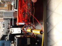
I don't have much more time to look at this today. I would strongly suggest that if you want help from the forum you bite the bullet , disconnect the standoffs from either boards or chassis, flip the boards and take clear focused straight-on photos of both top and bottom sides , taking care to make sure everything on the board is shown , which means taking a shot from a different point of view whenever one part or detail is hiding behind another.
All too often people get on asking for help and then measure out the needed info in minimal bits and pieces , making it harder than it should be every step of the way. Take the time and I'm sure you'll get all the help you could need. Patience was the biggest lesson I had to learn when I started electronics with building kits years ago. Not naturally inclined to dispassionate checklisting, it took me a long time and a lot of building to appreciate the method. Still poor at it though : ).
I'm a little surprised to see that Audio Note doesn't supply sockets for the power tubes.
I don't have much more time to look at this today. I would strongly suggest that if you want help from the forum you bite the bullet , disconnect the standoffs from either boards or chassis, flip the boards and take clear focused straight-on photos of both top and bottom sides , taking care to make sure everything on the board is shown , which means taking a shot from a different point of view whenever one part or detail is hiding behind another.
All too often people get on asking for help and then measure out the needed info in minimal bits and pieces , making it harder than it should be every step of the way. Take the time and I'm sure you'll get all the help you could need. Patience was the biggest lesson I had to learn when I started electronics with building kits years ago. Not naturally inclined to dispassionate checklisting, it took me a long time and a lot of building to appreciate the method. Still poor at it though : ).
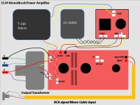
Hi Craig, yes I have it wired exactly per the diagram here. (with grounding - black wire connecting negative speaker terminal to grounding pad on the driver board). That said, it seems interesting to me that there is only one red wire to connect the 8ohm speaker terminal to the driver board, but nothing to connect the 4ohm terminal. At this point I'm quite sure that the issue is not one of wiring... I'm thinking there may be a bad (or bridged) solder possibly on a resistor or diode or cap.
Now that I've reversed the A1 and A2 wires on (we'll call it #1 amp), I'm going to do voltage checks again on the 2nd amp... if voltage checks check-out like I expect them to... does that mean we can rule some other thing(s) out?
Thanks again gentlemen for all your help!
Now that I've reversed the A1 and A2 wires on (we'll call it #1 amp), I'm going to do voltage checks again on the 2nd amp... if voltage checks check-out like I expect them to... does that mean we can rule some other thing(s) out?
Thanks again gentlemen for all your help!
Attachments
Have you tried replacing the tubes with known good tubes?
Check here for microphonic tubes.
Checking for Microphonic Tubes | Rivera Amplification
Check here for microphonic tubes.
Checking for Microphonic Tubes | Rivera Amplification
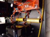
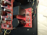
OK Andrew, I had a look at all of the pictures. First thing that I noticed was the soldering. Many of the resistors and other components do not have through holes completely filled with Solder. This is bad. you need either more heat, or to hold a soldering iron on longer, the entire whole should be filled with solder and it should make a small mound on both sides. Also, what is the bundle of wires under the power supply board that is wrapped in black tape? Electrical tape is something that should not be in a tube amplifier, it is a very hot place in there and that is not a permanent way to isolate wires. Please don’t take these critical points personally, I’m just trying to help you be able to enjoy your amp This is a very expensive kit to start with, it takes quite a lot of experience and knowledge to make something like this properly. You should definitely try running the amplifier without the negative feedback attached. I still believe it’s a issue related to wiring, or the feedback.
Last edited:
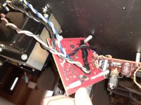
I just looked at the photos, yes- holes not filled like mctavish says.
I would start with a clean hard copy of the amp.
Take a highlighter pen and start going thru your work, In particular making sure you have the correct component in place (values , orientation,etc), touch up soldering joints.
Mark off- highlighter that section, then move on.
I would start with a clean hard copy of the amp.
Take a highlighter pen and start going thru your work, In particular making sure you have the correct component in place (values , orientation,etc), touch up soldering joints.
Mark off- highlighter that section, then move on.
Wow, very glad to have all the input from you all. Firstly, yes my soldering was not pretty though I never considered that it wouldn't at least be effective enough to create a connection. I'll go back and touch things up for sure.
I've discovered something kinda dumb that I forgot to do which was to bend the grounding post on the RCA signal input forward so as to not be touching the chassis. This is done now.
I have not tried replacing the tubes, these are the cheapy ones supplied. ((I've been told this is a better way to go during the build process as using nice expensive tubes can easily get blown up unnecessarily until the amps are confirmed A-ok and have some burn-in time)). this made good sense to me.
Spacing between the board and the components.... This is a bit of a sore spot as spacing was not mentioned in the original manual.... being a newby, I didn't know about spacing issues (until after soldering the board was complete). I HAVE however, gone back and lifted up/re-soldered resistors that go over board traces. I have not lifted anything else. I believe Brian at ANK kits mentioned that spacing was only required for components that go over board traces.
Thank you for the advice regarding the terminated (brown and black/green) wires under the power supply. According to ANK, these wires are only required for the level 3 version of the kit... since that one has tube rectification. I will terminate these properly.
I'm going over each resistor and confirm measurements for each.
- Status
- This old topic is closed. If you want to reopen this topic, contact a moderator using the "Report Post" button.
- Home
- Amplifiers
- Tubes / Valves
- EL34 monoblock kit build... troubleshoot