In short, I have a London City Bulldog tube amplifier. However, this is a "cheap" copy of a Marshall JCM2000 DSL100, which have been marketed in different versions. Another well-known is the Ashton VP100. A slightly different jacket, but identical on the inside to the London City Bulldog.
Now years ago I had the problem that the amplifier pumped loud pops and rumble from speakers when the standby button was turned on.
Turning the level knob all the way to "0" did not change the volume at all. The creaking and popping remained just as loud.
Can't fix the problem at the time. Then put the amplifier in the corner and no longer used. Now I want to get the amp to work again and I have dusted it again. Now the "noises" seem to be as good as gone, but I do hear a constant hum coming from the speakers. This cannot be eliminated by turning the level to "0".
The volume has dropped drastically. Now I have to turn the level knob more than half way to get a little sound. Where normally the whole street would complain if it was on this level.
Then disassembled the amplifier and now I see next, a number of suspicious capacitors. 2 of which have already burst from the jacket.

The capacitors that have clearly visible burst are the capacitors for the heaters of V1 and V2.
With the other blue capacitors I see no bulging over mess around the capacitors.
To be on the safe side I replaced all the capacitors.
Unfortunately, there is no improvement yet regarding the constant hum coming out of the speaker and the huge dip in the volume.
In any case, I have now excluded that it is in the capacitors. I also measured on the points indicated in the diagram. See image below. instead of +444V I measure +464.6V and where +432V I measure +462.3V. Where I should measure -36V, I measure -39V.
+464.6V compared to +444V seems to me within the margins.
However, I find the difference of +462.3V and +432V. Because the difference in the schematic between those 2 points is 12V. And I only measure a difference of 2.3V.
Is this curious?
What is even more remarkable (or not) is that there is a loop level switch on the back. And when I put a jumper cable in the send and return, I don't notice any difference when I switch this switch on or off.
When I put a pedal between the send and return, it boosts the sound. Is this correct?
I know, there are a lot of questions but I don't know where to look ...
So briefly the problems I have:
1. Volume dropped drastically
2. Constant hum on the speaker. (does not respond to knobs)
Does anyone have experience with this amplifier or related or can someone help me with troubleshooting, I would like to hear it.
Thanks in advance.

Now years ago I had the problem that the amplifier pumped loud pops and rumble from speakers when the standby button was turned on.
Turning the level knob all the way to "0" did not change the volume at all. The creaking and popping remained just as loud.
Can't fix the problem at the time. Then put the amplifier in the corner and no longer used. Now I want to get the amp to work again and I have dusted it again. Now the "noises" seem to be as good as gone, but I do hear a constant hum coming from the speakers. This cannot be eliminated by turning the level to "0".
The volume has dropped drastically. Now I have to turn the level knob more than half way to get a little sound. Where normally the whole street would complain if it was on this level.
Then disassembled the amplifier and now I see next, a number of suspicious capacitors. 2 of which have already burst from the jacket.
The capacitors that have clearly visible burst are the capacitors for the heaters of V1 and V2.
With the other blue capacitors I see no bulging over mess around the capacitors.
To be on the safe side I replaced all the capacitors.
Unfortunately, there is no improvement yet regarding the constant hum coming out of the speaker and the huge dip in the volume.
In any case, I have now excluded that it is in the capacitors. I also measured on the points indicated in the diagram. See image below. instead of +444V I measure +464.6V and where +432V I measure +462.3V. Where I should measure -36V, I measure -39V.
+464.6V compared to +444V seems to me within the margins.
However, I find the difference of +462.3V and +432V. Because the difference in the schematic between those 2 points is 12V. And I only measure a difference of 2.3V.
Is this curious?
What is even more remarkable (or not) is that there is a loop level switch on the back. And when I put a jumper cable in the send and return, I don't notice any difference when I switch this switch on or off.
When I put a pedal between the send and return, it boosts the sound. Is this correct?
I know, there are a lot of questions but I don't know where to look ...
So briefly the problems I have:
1. Volume dropped drastically
2. Constant hum on the speaker. (does not respond to knobs)
Does anyone have experience with this amplifier or related or can someone help me with troubleshooting, I would like to hear it.
Thanks in advance.
Measure the HT with your meter on AC volts. Have you got a sig gen and scope? Soundcard scope is a good free PC based sig gen, scope etc if not. Trace a signal from IP to OP, big loss of OP sounds more like a voltage amplification stage, but it could be anything from a dry joint to out of spec resistor to a tired valve, hard to tell from this distance.
Andy.
Andy.
Yes I have a signal generator and oscilloscope. Okay, so I put a 1kHz signal on the input and measure from the input to the output? Of course I have to take into account that when I measure the preamp tubes on the anode, I do this after the decoupling capacitor. Isn't this right? Otherwise my scope is not going to like it that much, I expect.Measure the HT with your meter on AC volts. Have you got a sig gen and scope? Soundcard scope is a good free PC based sig gen, scope etc if not. Trace a signal from IP to OP, big loss of OP sounds more like a voltage amplification stage, but it could be anything from a dry joint to out of spec resistor to a tired valve, hard to tell from this distance.
Andy.
For V1a this is after C6.
Did you try another 12AX7 for V4 allready ? (exchange with one of the others)
Could be a leak heater-cathode.
Mona
Not yet. I can try that too.
I can see that for V3 and V4 a 12AT7 has been used instead of a 12AX7.
While the schematic only prescribes a 12AT7 for V3. Is there a good reason to use a 12AT7?
I still have new 12AX7 tubes. Can it just be changed for that?
You can't just put an 12AT7 in for V4 without changing R93 (470Ω).Incidentally, just swapped V3 with V4 (12AT7). This made no difference.
That tube needs ~1k2 for R93.
I guess the common cathodes are ~45V above ground if all is well.
Mona
You can't just put an 12AT7 in for V4 without changing R93 (470Ω).
That tube needs ~1k2 for R93.
I guess the common cathodes are ~45V above ground if all is well.
Mona
Just checked and R93 is indeed 470 ohms. You say that this is not good anyway. So should I replace this tube for a 12AX7? An AT version does not belong here?
No, I checked, it's ok too.Just checked and R93 is indeed 470 ohms. You say that this is not good anyway. So should I replace this tube for a 12AX7? An AT version does not belong here?
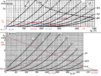
The 1k2 was to get the same anode currents as with the 12AX7.
The 12AT7 can go much lower with the Va, the extra drop on the Ra (higher Ia) is no problem.
Draw some load lines to be certain. It's with Rk=1k for the 470Ω case anode 2k4 for 1k2 since the resistor is common to the two triodes.
To see if the hum is from the V4, try without it, if still hum it's the final stage.
Mona
Attachments
Just taken measurements with an oscilloscope. The measurement results have been put in the schematic below. What strikes me is that the preamp does what it should do. Although I think it is strange that when the level knob is turned up, the signal is cut off. This is not the case at a lower level. I don't think this is right?!
Then measured further after the Master potentiometer. Here we get to see a nice sinewave again. But then after V4 it seems to go wrong. The entire bottom of the sinus is cut off. And this is reflected in the output.
I also turned the master all the way back to 0. Then zoomed in on the signal and then there still seems to be a 100Hz hum. I expect it is also this one that I hear.
Please send your feedback on my measurement results.
Doesn't look very nice.
Problem is, the feedback is trying to correct the result (or is suposed to), so it could be the feedback misbehave.
If you disconnect R102 (47k) there is no FB, gives more insight where it goes wrong.
Or is it the inductor formed with the IC4 (evt a source of hum), disconnect C65 (10µF) to put the IC4 out of the circuit.
Mona
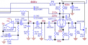
Just measured the indicated points. Note, I mirrored V4 in the drawing. In practice it turned out to be correctly mirrored. Does not matter for the calculation and operation.
But the measurement deviates after R95 and R94 from what you indicate. So the DC settings on these points already seem to be wrong.

But the measurement deviates after R95 and R94 from what you indicate. So the DC settings on these points already seem to be wrong.

- Status
- This old topic is closed. If you want to reopen this topic, contact a moderator using the "Report Post" button.
- Home
- Amplifiers
- Tubes / Valves
- Problems with London City Bulldog / Ashton VP100 tube amp