Ha, this is great! I know there's a reason why these tubes aren't used and I thought all the replies would be "this is silly, don't even think about it", but with all the ideas here I really want to try. Even if it turns out to be sub-optimal, I will at least have learned something. I have pretty much everything I need except for the sockets.
@GoatGuy - Is this something like what you suggested?
@GoatGuy - Is this something like what you suggested?
Attachments
Last edited:
@GoatGuy - Is this something like what you suggested?
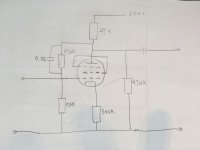
Prey don't ... GoatGuy said a *series R + C* , your drawing has a *parallel RC* , which would cause part of plate voltage to appear at the input and at g1 (!), microfarads of input capacitance and no output at best ...
Also put a resistor between screen and plate, 100R ... 1K, and another resistor in series between the control grid and anything else directly soldered short to the g1 pin. These are grid stoppers as a precaution against parasitic oscillation. They may not happen but if they do you will get confusing results from your prototype.
Last edited:
O.K but your resistor values need some corrections, too.
With your numbers I get only 45V on the plate and gain 11x with 200V supply.
We only have plate curves for 100V screen.
From that we can calculate triode numbers for 100V plate and 100v screen, right ...
Now we have multiple choice, and when we fix arbitarily supply voltage to be 200V,
and shoot for a couple of negative control grid voltages we get:
g1=-4V @Vp=100V, Vs=100V, we get Ip=3.5mA, requires Rc=1.2k, Rp=27k, gain=6x
g1=-3V @Vp=100V, Vs=100V, we get Ip=5mA, requires Rc=600R, Rp=20k, gain=7.5x
g1=-2V @Vp=100V, Vs=100V, we get Ip=7mA, requires Rc=270R, Rp=15k, gain=9x
g1=-1V @Vp=100V, Vs=100V, we get Ip=9mA, requires Rc=120R, Rp=10k, gain=10x
Resistor values are calculated straight from plate curves and ohms law.
To get the gain numbers I made the assumption that 6DA6 is a similar remote cutoff tube as your EF9 and did a quick spice simulation. 6DA6 is way more modern than EF9 but DC numbers matched the EF9 curves quite well. And I also kept your 470K+0.22u feedback from plate to grid thingy ... It actually doesn't seem to do much in my sim ...
Also, if your input is 1V peak-to-peak, expect THD around 1.5%, your setup came up with 1.8%.
Numbers may be higher in reality ...
Last edited:
Ha, this is great! I know there's a reason why these tubes aren't used and I thought all the replies would be "this is silly, don't even think about it", but with all the ideas here I really want to try. Even if it turns out to be sub-optimal, I will at least have learned something. I have pretty much everything I need except for the sockets.
@GoatGuy - Is this something like what you suggested?
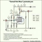
As Sorento notes, the configuration I had in mind is with the R, C in series, per this belated diagram.
I just drew it, so I've not yet quite vetted the quiescent values. This is however for the EF 9 valve.
⋅-⋅-⋅ Just saying, ⋅-⋅-⋅
⋅-=≡ GoatGuy ✓ ≡=-⋅
Attachments
As Sorento notes, the configuration I had in mind is with the R, C in series, per this belated diagram.
R3 should be connected to the other side of R10, no?
R7/R8 do not add any linearization they just attenuate the output signal;
The capacitor symbols are backwards.
R3 should be connected to the other side of R10, no? R7/R8 do not add any linearization they just attenuate the output signal; The capacitor symbols are backwards.
[1] R₁₀ is a “grid stopper” anti-oscillation function. R₃ (470 kΩ) is NFB, but being on the grid-pin side of R₁₀ … seems to me to be undermining the grid-stopper's purpose a bit.
[2] R₇ and R₈ indeed are an attenuator. With the helpful 'feature' of also sturdying up output impedance by R₇ || R₈, or in this case (10 × 39) / (10 + 39) = 7.9 kΩ output impedance. Nice!
[3] Sadly, my capacitor schematic elements are always drawn backward. I'll fix these up, and try to change the library as well, since I created the darn thing. Regardless, I do try hard to ensure the + is on the right pin tho!
Thank you for your review and commentary, MerlinB.
Much appreciated.
⋅-=≡ GoatGuy ✓ ≡=-⋅

This brings back memories! The EF 9 and EL3 were the first tubes I built an amplifier with. I was 12 yrs old and had a 12 yr older brother who always built his own amps and tape recorders so that and the fact that he had several books about radio's and amplifiers helped a lot.
The EF9 and EF 22 can certainly be used for hifi quality amps. Comparing nine pin penthodes (like EBF 80) with them showed practically the same distortion figures. Don't forget people use other pre war tubes like 6SJ7 these days with good results (Hiraga for instance).
Some data
Vb 250v
Ra 100k
Rg2 390k
Ia 1,6 ma
Ig2 0,45 ma
Vo eff 10v
G 85
D 2.5 %
A pentode operating as a pentode, with a CCS load makes the output impedance extremely high.
That means the wiring and next stage load impedance will affect frequency response and gain.
If you want to use the same Pentode and a CCS load, do as Tubelab_com said: Triode Wire the Pentode.
Remember, the plate impedance, rp of a triode wired pentode (just like a real triode) will be increased by (u + 1) times the un-bypassed cathode self bias resistor.
Example:
A triode wired 6AU6 has u = 20, and rp = 7,700 Ohms.
With a 300 Ohm un-bypassed cathode self bias resistor, the new plate impedance, rp, will be:
7,700 Ohms + ((20 + 1) x 300) = 7,700 + 6,300 = 14,000 Ohms.
The impedance of a good CCS which is in parallel with 14,000 Ohms almost drops out of the picture.
You will have 14,000 Ohms driving the next stage.
Just my opinions
- Home
- Amplifiers
- Tubes / Valves
- Variable-mu madness