Hello,
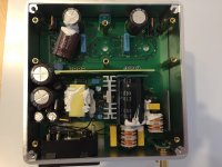
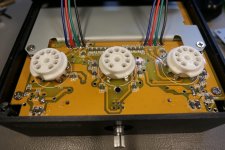
I recently purchased a Tubecube7 from Tubedepot. I also brought some upgraded tubes. Today I took off the bottom of the amp. To my surprise, I see that this particular unit (which still had its warranty sticker firmly in place) has been modified.
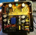
Comparing to other photos of the miniwatt n3, and a rogue schematic if found online, it appears that the cathode biasing circuit which I thought was a current source, has not been stuffed on my board, and some other jumbers installed etc. The power supply looks unmodified.
-Top right corner, no TO-92 device or TO-220 case device stuffed.
- Black jumper wires around the 12AX7 socket.
- Some traces drilled out to disconnect them from others.
- No time to look at the other side but I suspect that we just have a cathode resistor bias.
Questions:
1. Have any of you seen this is a recent Tubecube7?
2. I am suspicious that this was done for cost reduction, but there may be other reasons.
3- I am still building my full-range efficient speakers to go with this amp and my rebuilt p-p EL84 amps, so I haven't listened to it. Does it perform as well as the original? My guess is no.
4- Does anyone have an accurate schematic of a Miniwatt n3 of Tubecube 7? My searching has been fruitless.
I would appreciate any insight anyone may have.
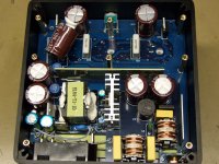
I have attached a photo of my Tubecube7 and a photo of a Miniwatt n3
-david BTW
I recently purchased a Tubecube7 from Tubedepot. I also brought some upgraded tubes. Today I took off the bottom of the amp. To my surprise, I see that this particular unit (which still had its warranty sticker firmly in place) has been modified.
Comparing to other photos of the miniwatt n3, and a rogue schematic if found online, it appears that the cathode biasing circuit which I thought was a current source, has not been stuffed on my board, and some other jumbers installed etc. The power supply looks unmodified.
-Top right corner, no TO-92 device or TO-220 case device stuffed.
- Black jumper wires around the 12AX7 socket.
- Some traces drilled out to disconnect them from others.
- No time to look at the other side but I suspect that we just have a cathode resistor bias.
Questions:
1. Have any of you seen this is a recent Tubecube7?
2. I am suspicious that this was done for cost reduction, but there may be other reasons.
3- I am still building my full-range efficient speakers to go with this amp and my rebuilt p-p EL84 amps, so I haven't listened to it. Does it perform as well as the original? My guess is no.
4- Does anyone have an accurate schematic of a Miniwatt n3 of Tubecube 7? My searching has been fruitless.
I would appreciate any insight anyone may have.
I have attached a photo of my Tubecube7 and a photo of a Miniwatt n3
-david BTW
Attachments
Last edited:
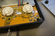
Well they are not the same layout. The wires were probably corrections of mistakes made in trying to copy the miniwatt. Or they are just using a different filament voltage than originally designed on the pcb. The power supply is very different in component choice as well as layout. It maybe the same circuit, but probably is modified. Cant make any judgement on the to220 being missing, but they could have been regulators for the heaters and the modified power supply design regulates in a different spot. The new wires connect to heater pins on the tubes.
Hello vanofmonks
Thanks for your response. I agree that the wires appear to be filament wiring. I have not completely disassembled the unit pending feedback from the seller to determine if current stock are all like this or is this an anomaly. It mine is an example of what China is shipping, then I will probably keep it.
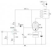
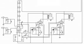
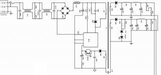
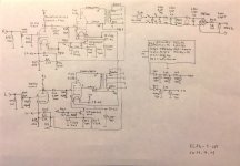
I have what is purported to be the original APPJ_PA0901A. The schematic I have clearly shows current source biasing for the EL84 cathodes. I also have another drawing which is supposed to be a simplified miniwatt N3 diagram. Both of them show a current source.
I am pretty sure that the TO-220 was the power MOSFET in the current source. In any event, the two schematics attached are roughly consistent with each other, but one without any values.
-david BTW
-david BTW
Thanks for your response. I agree that the wires appear to be filament wiring. I have not completely disassembled the unit pending feedback from the seller to determine if current stock are all like this or is this an anomaly. It mine is an example of what China is shipping, then I will probably keep it.
I have what is purported to be the original APPJ_PA0901A. The schematic I have clearly shows current source biasing for the EL84 cathodes. I also have another drawing which is supposed to be a simplified miniwatt N3 diagram. Both of them show a current source.
I am pretty sure that the TO-220 was the power MOSFET in the current source. In any event, the two schematics attached are roughly consistent with each other, but one without any values.
-david BTW
-david BTW
Attachments
I think it is very possible that the ccs fet is probably a smt device on other side of the board. There are a significant amount of resistors and other components not visible on either board from the pic and also there are no solder points on the viewable side, so they must be smt devices on the other side. That would also explain why there are so many resistors in series as the anode load of the 12ax7, they are using low wattage smt resistors. The yellow board had footprints for a to-220 and to-92 size fet. The to-92 fet is missing from the blue board, so it is not unreasonable to believe there is an smt fet also added as an option and that is what they are doing. Also, the blue board has 12v heaters and the yellow has 6v heaters. Can't say why they changed that or how the rest of the circuit changed due to that, but it is not fully compatible with the full schematic you have. I suspect the audio portion of the circuit is similar to the schematic though, it just uses a smt fet. It's possible that your version is quieter due to not running the heaters off the output cathode circuit.
I attach pictures and schematic of the appj pa0901a I bought in 2015. Hope it helps. The To92 part is the TL431 regulator and the TO220 part is the mosfet. They are unprotected against tube shorts and maybe they have been removed on later units to avoid customer returns, I guess.
Attachments
Thanks very much for the hand-drawn schematic. It matches what I was expecting. I have learned much with your help.
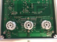
I was able to get a second brand-new Tubecube7 and it is identical to the photos I posted earlier, so I believe this is the currently shipping version. The other side of the board from my previous photos are attached here. As you can see, the voltage reference TL431 and the MOSFET are not present. There is a solder bridge, and some double stacked 1206 resistors in a few spots to replace the CCS biasing.
This photo basically confirms my suspicion that the CCS was removed. I have not made a hand drawn schematic, but I suspect standard cathode biasing. Based upon my recent research, it was my understanding that the CCS was a superior sounding design option and that it wouldn't drift with tube ageing. Or perhaps the suggestion of a quieter version is possible due to the different heater connection.
I would appreciate any thoughts or comments on the relative merits of the what we are seeing here.
-david BTW
Attachments

Last edited:
- Status
- This old topic is closed. If you want to reopen this topic, contact a moderator using the "Report Post" button.
- Home
- Amplifiers
- Tubes / Valves
- Tubecube 7 PCB Inspection?