Thanks again to Soundhappy for posting the Gold mine of Japanese DIY tube schematics. In post 365, see link, he posts the index and I've become a bit addicted.
https://www.diyaudio.com/forums/tub...-mine-di-audio-tubes-schematics-japan-37.html
This line stage using an output trannie, see attached, caught my eye. Impressions, opinions anyone?
Links to the articles:
MJ1512_(07)easy-obtain-tube-line-control-amp[plan]_OchiaiM.pdf - Google Drive
MJ1601_(08)easy-obtain-tube-line-control-amp[making]_OchiaiM.pdf - Google Drive
Attachments
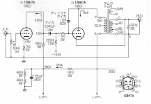
The 12BH7 plate resistance, rp, is about 5.3k Ohms.
Driving a 5 k transformer with an rp of 5.3k is probably too low of a load impedance.
If you use this as a line amplifier, and load the secondary with an amp input of say 10k Ohms, in parallel with the 200 Ohm resistor across the 16 Ohm tap, that is light loading (200/16 = 12.5).
You could argue that means the primary is now 5k x 12.5 = 62.5k; but that would not be true at at low frequencies, because the F475 primary only has enough inductance to work well at 20Hz, as a 5k load at mid frequencies.
At 20 Hz, the inductive reactance is probably only about 5k, that is about 40 Henries.
There are lots of tubes that drive a F-475, some are pentodes. But pentodes need negative feedback to drive the F475 at bass and low frequency.
One tube that does not require feedback is the DHT 45. But the 45 has a plate resistance, rp, of 1.7k, which is only about 1/3 of the 12BH7 rp of 5.3k.
Some will argue that the negative feedback loop on that circuit will fix the low frequency response, that may be true.
But the 12BH7 will have to work much harder at 50, 40, 30, and 20Hz. That means the harmonic distortion there will increase drastically trying to drive that inductance. Then the negative feedback will partially fix that, but some of the distortion of low frequencies will still be much higher than at mid frequencies.
Using a 45 and an F-475 is what some use as a low power amp to drive very efficient loudspeakers.
The problems with using a 45 is that they are expensive, and for line amp duty you must use DC on the 2.5V 1.5Amp filament (with extremely low ripple of the DC).
Tell us what you will use the line amplifier for . . . Input signal sources, and what the line preamp output will drive next.
Last edited:
Thanks for the response guys, much appreciated.
Let's suppose for the sake of argument, and economy of course, I would go with one of the Edcor ESE or Hammond 125?SE OPTs. I'm not about to plunk down big bucks on a Japanese trannies for what would be an experiment.
I have, I think, three options:
1. Double the size of the resistor across the OPT secondary,
2. Double the OPT primary impedance or,
3. Parallel two sections of a 12BH7.
Thoughts please. Thanks, Steve
That output xformer will need to have a core gap to avoid saturating due to the DC flowing through the primary.
In general, it's not my favorite design. Transformer coupling the output is a great idea in a line stage, but this thing defeats the point by grounding one side of the secondary.
My inclination is to replace the second stage with a cathode follower. If you want a transformer on the output, do it right and use it for balanced XLR (Or TRS) outputs and capacitively couple to it.
A design like I described should have distortion across the spectrum of well under 0.1%.
Safety first, ground the secondary.
Prevent surviving spouse syndrome.
And, grounding of the secondary is necessary if you use cathode feedback from the secondary. Another circuit without that ground, needs to use another form of negative feedback.
If you need a balanced (ungrounded) output, then use a transformer that is made for Plate primary, to balanced output (that is UL or otherwise safety approved). Not inexpensive.
Doubling the 200 Ohm resistor will only make the total low frequency roll off earlier. The inductance of the transformer primary is the dominant cause of the low frequency limit.
Using parallel 12BH7 triodes is a good idea.
Use individual grid stoppers at each socket grid connection.
Use individual self bias resistors for each cathode to balance the currents.
Each tube will see an easier load (shared).
Single ended transformers do have the required air gap.
There are some line amps with cathode follower outputs with RC coupling that can blow a solid state amp.
The same can be said for some plate output stages and RC coupling to the output.
They also may cause a solid state amp to blow out.
Check those kind of circuits for transients at these times: Power up, Power down, and Hot start (mains power glitches off for a brief period, and then back on before the cathodes are cold).
Check this out before connecting to a solid state amp.
Last edited:
I don't understand this fascination with old Japanese designs. Poor linearity, no grid stops, improperly used output transformers, cultish designs. WTF?
This stuff gives valve audio a bad name, and it deserves it to the extent that this is considered desirable.
All good fortune,
Chris
This stuff gives valve audio a bad name, and it deserves it to the extent that this is considered desirable.
All good fortune,
Chris
Isn't the OPT secondary grounded at point 'E'?
It looks like the secondary is wired in opposite polarity from normal, with the 16 ohm tap grounded and the common tap connected to the load.
If you use 5687 instead of 12BH7, you could get its rp down to maybe 2k ohms, which would let that 5k primary look like a lighter load. You'd have to adjust the bias voltage, change parts values, etc. to make that work.
--
Chris,
Point taken about the cultish designs. Actually if you take a look at some of Soundhappy's links this one of the less wacky. The two Japanese mags that are linked to make 300B designs seem quite pedestrian. Transformers and chokes must be inexpensive in Japan judging by the quantity and sizes used in many designs. Would you believe a 6V6 P-P design with TWO interstage trannies, plus the OPT?
Grid stoppers would be the first item on my list to add to the design.
Thanks all.
Steve
Using an RC coupled cathode follower line stage does require a muting circuit to deal with the transient on power up. Such a circuit is quite simple to design and solves that problem.
The way I was suggesting the use of an output transformer was completely different. My suggestion was to design this as if it was going to be used with no output transformer, then simply add a relatively small line transformer (something like a Jensen) to give galvanic isolation and a differential output.
Lots of line stages are designed with no transformers in the signal path, but I like to have differential outputs on a line stage if I can.
I don't understand this fascination with old Japanese designs. Poor linearity, no grid stops, improperly used output transformers, cultish designs. WTF?
This stuff gives valve audio a bad name, and it deserves it to the extent that this is considered desirable.
All good fortune,
Chris
There are some interesting ideas, and a few gems among them. It's worth looking at some, but best not to get carried away.
Isn't the OPT secondary grounded at point 'E'?
It looks like the secondary is wired in opposite polarity from normal, with the 16 ohm tap grounded and the common tap connected to the load.
If you use 5687 instead of 12BH7, you could get its rp down to maybe 2k ohms, which would let that 5k primary look like a lighter load. You'd have to adjust the bias voltage, change parts values, etc. to make that work.
--
Yes, but he is using the output winding as cathode feedback.
That output xformer will need to have a core gap to avoid saturating due to the DC flowing through the primary...
Some of the 6mA bias current through the primary also runs through the secondary, after being split with the 220R resistor across the secondary. Possibly, this is done to help cancel some the core bias magnetization? Also, it would seem to force some amount of unblocked D.C. offset at the secondary, and so, at the output Jack.

Ken,
I thought of the DC offset too. Nut 6mA times say a secondary resistance of 0.3 ohms is about 2mV. Worth worrying about? (question meant seriously)
Steve
Hi, Steve,
Maybe not. It depends on the amplification of the succeeding power amp.
Sorry, a bit more than unity gain. Digital source, for the most part, and tube power amp with a "normal" input sensitivity.
If I'm reading this schematic correctly, this is going to have a whole lot more than unity gain, probably too much so.
...a bit more than unity gain. ...
As drawn, gain is nearer 8.
And the BIG "feature" is that it can drive 600 Ohms, even 32 Ohms, with no stain. Is that in your design requirements?
If you only drive "normal hi-fi loads", you could save a BUNCH of bucks and pounds with a simple mod. If the chassis looks bare, get some "vintage transformers- as-is" off eBay and nail them on.
Attachments
- Status
- This old topic is closed. If you want to reopen this topic, contact a moderator using the "Report Post" button.
- Home
- Amplifiers
- Tubes / Valves
- What's right, or wrong, with this line stage