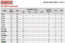
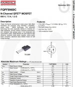
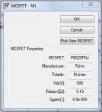
Received a dozen of Fairchild FQPF8N60C today. LTspice has no model for this FET but I read here one could be produced from the datasheet. Has anyone experience with this job? The sheet doesn't hold all info for completion, educated guesses are welcome.
Attachments
Last edited:
Ever tried of bootstrapping the gain stage?
Split the anode resistor in two equal resistances and couple the output of the CF to the midpoint of these resistances with a capacitor..
The voltage over the resistance will be constant so the current will also be constant.
As a result gain will be very close to the Mu of the tube and distortion will be lower. The anode load behaves as a very high resistance.
As a CF I would use the ECC88 or similar at around 10mA (see the datasheet as it is a recommended bias point).
I recently experimented with an adjustable gain stage using the two triodes of a 12ax7 followed by a CCa (luxury ecc88 sold way overpriced but it was the only ecc88 like tube I had around)
First stage used the normal grounded cathode amplifier using Ra 220k and Rk 1k5 with a cap in parallel and 15k in series to ground for feedback.
Second stage was with two 100k resistors for Ra and Rk was just 1k5 with a cap in parallel. The grid was capacitor coupled to the output of teh first stage.
The third stage was the ECC88 (CCa) as a CF direct coupled to the output of the second stage and Rk was 10k to ground (used a 5W resistor for that one)
The output of the CF was coupled with a cap to the second stage middle of the anode resistors (bootstrap).
Then the output of the CF was coupled with a resistance to the feedback input at the kathode of the first stage so you could adjust gain.
Supply voltage used was 300v
this worked very nice actually. In a load of 10k I was able to get around 45vrms. And just as an experiment I tried a 1k load and got around 7vrms.
Also the output impedance is very low. changing from no load to 1k load almost didn't change the output voltage (as long as it didn't clip of course....).
Got to start a topic around this gain stage soon.
I simulated it first also and simulating the output impedance in Ltspice it was only 7ohm or something. Maybe this is optimistic but it's low enough
What really impressed me is how good the bootstrapping can work and it's almost never seen... The psrr is alot better
It's just an idea...
The 6c45 as CF is also a good choice. it's even better then the ecc88 but for driving just the input of a SS amplifier it wouldn't make much difference I think
Last edited:
I haven't and perhaps I'll try one day as seven ohm output impedance is impressive for a tube built. High PSRR is practical (hence the MOSFETS as I need two PSUs) but three stages and high GNF does not appeal to me as such, although it would undoubtedly measure excellent. What I'm after here is "the sound of the good ol' 82" and the urge to use 6c45. I'll keep an eye open for your thread to come.
But OnSemi has. Try Here... LTspice has no model for this FET but I read here one could be produced from the datasheet...
Last edited:
Thanks for the tip Indra, it's location is here: https://www.onsemi.com/pub/Collateral/FQPF8N60C.lib If someone would be looking for a tutorial, Simon Bramble did a nice job.
I would have just used one ECC82 instead of two different valves.
I am a big fan of the ECC82.
Me too !!! As a u follower , 12AU7 is amazing !!!
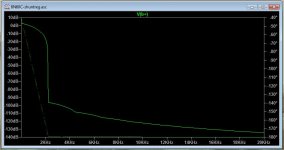
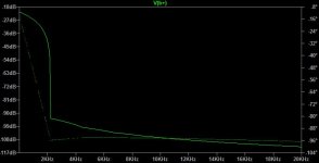
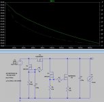
what's happening below 2KHz
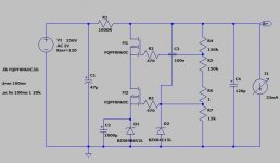
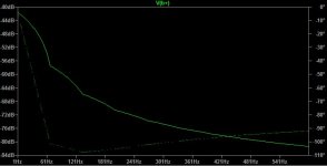
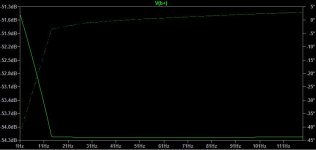
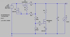
I found two errors in simulation and schematic:
- R7 too small, the lower NFET can not conduct
- number of simulation points were 100m (=0.1), should be bigger, 100 for example
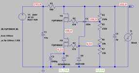
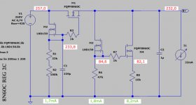
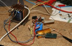
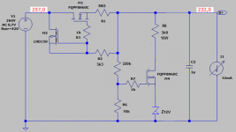
The former regulator design was not satisfactory so I did a makeover. Output voltage was not very stable over time and there was too much slack. Now a series regulator replaces the large resistor I had before and a tout-simple shunt reg finishes the job. It runs very stable after a turn-on delay of circa 1 minute (because of C1 size). I was unable to measure any output ripple with 730mV in. Still have to measure its output impedance by varying the load. When building, resistors 1 and 6 might need some tweeking (because of part tolerance) to arrive at the intended voltages. Output voltage is set by R1 only. R2 should be 1W, R6 also, R8 should be 5 to 10W.
One thing struck me as odd. As depicted in some old screenshots I saved, the amount of deciBells dropped dramatically. I don't know if it's a software bug or I really hit a deep null here. Simulation files are attached, so one can find out for one self.
One thing struck me as odd. As depicted in some old screenshots I saved, the amount of deciBells dropped dramatically. I don't know if it's a software bug or I really hit a deep null here. Simulation files are attached, so one can find out for one self.
Attachments
Last edited:
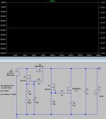
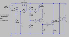
Indeed, he has put a voltage source in place of a current source and vise versaWell, your "regulator" does not work at all.

Mona
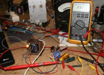
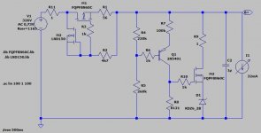
5,5mA slack, 243V in and 237V out, the zener is at 47mW. Output impedance would be around 50 ohm (0,1V/2mA). Better than my setup which simulated 420R . I have some PNPs in stock (2N5401, 2N6520, MPSA92, MPSA94), let's put that HFE in action...
. I have some PNPs in stock (2N5401, 2N6520, MPSA92, MPSA94), let's put that HFE in action...Attachments
Last edited:
What is your actual circuit diagram ?
That LT Spice circuit you posted (8N60shuntregV2C) do not work.
And what kind of performance you look for ? (voltage, current, ripple rejection, Rout)
All good things are welcome but the power tranny is limited to 50mA and its secundary measures 290R. Parts count and heat should be kept moderate as I need two of these PSUs in a small casing. It is intended for the above rather constant current circuit which has mediocre PSRR so ripple rejection should be paramount.
Last edited:

- Status
- This old topic is closed. If you want to reopen this topic, contact a moderator using the "Report Post" button.
- Home
- Amplifiers
- Tubes / Valves
- ECC82 pre with cathode follower