Prior to modifying the entire circuit, it might not be a bad idea to try dropping in a new RIAA passive network conforming to the modern understanding and using superior components than Lafayette chose. That might deliver quite listenable performance without a lot of effort.
For example, Bonsai's:
Full paper here:
Or Lipschitz and Jung:
NB: I just now performed a search to find those, as I have electronic copies which are too large to post, so the links work today but are not guaranteed to be forever stable.
Numerous other papers on the subject of inverse RIAA do, of course, exist, but caution is urged as many have been discredited since publication. The modern age delivers far better simulation results than were previously possible.
For example, Bonsai's:
An Accurate Inverse RIAA Network
An Accurate Inverse RIAA Network
December 14, 2017
Designing and engineering RIAA equalizers demands a clear understanding of the signal chain requirements during the development process. Once components have been committed to a prototype PCB however, testing is required. Presented here is a simple Inverse RIAA Network, or IRN, that allows testing to be quickly and effectively done.
It is important that the RIAA equalizer response is not only accurate across the audio band (20 Hz to 20 kHz), but also well behaved beyond that. The usefulness of this simple tool can be gauged by the fact that, after building an RIAA EQ amp based on a design published by one of the foremost exponents of the art, testing revealed that, whilst its sine wave response conformity from 20 Hz to 20 kHz was exemplary, the gain at 500 kHz was 8 dB higher that at 20 kHz, which manifest as overshoot on the square wave tests. Some simple mods to the RIAA network resolved the problem, and the response was then flat out to ~50 kHz, after which it dropped off at 20 dB/decade.
Full paper here:
Or Lipschitz and Jung:
https://cdn.shopify.com/s/files/1/0635/1487/files/lipshitz_jung_inverse_riaa.pdf
A High-Accuracy Inverse RIAA Network
Stanley P. Lipschitz and Walt Jung
Audio Amateur
January 1970
READERS WILL BE AWARE of the recent correspondence between the two authors regarding RIAA equalization in phono preamplifiers1·2. This has led to a re-examination of many familiar circuits, and has shown the need for changes and corrections to many of these in order to improve their accuracy. Extremely high accuracy can indeed be achieved by careful design, such as in the Jung-White modification of the Dynaco PAT-53, and many readers may be interested in having available an inverse RIAA circuit of sufficient precision to enable them to measure the deviations of phono preamplifiers to a high order of accuracy, as well as to conduct critical listening tests.
NB: I just now performed a search to find those, as I have electronic copies which are too large to post, so the links work today but are not guaranteed to be forever stable.
Numerous other papers on the subject of inverse RIAA do, of course, exist, but caution is urged as many have been discredited since publication. The modern age delivers far better simulation results than were previously possible.
Many thanks for that, looks like I have some reading to do.
You're welcome.
I am fairly sure that I couldn't make it sound any worse than it does at the moment.
Oh, never say that. It may always become worse. The ChiFi units always serve as inspiration for how trivial it is to make a tube amplifier sound execrable.
The house-brand tube units sold by Lafayette and similar companies appear to all originate with roughly the same Japanese designs, sheet metal, and iron, with the sheet metal slightly modified between resellers. Nothing is inherently wrong with these units, they often only need some circuitry improvements. I have a bunch of receivers either made or designed in Japan sitting on a shelf, all awaiting teardown and rebuilding. A daunting task given the mess underneath the chassis.
As long as you're doing the work. I suggest removing the death caps. Also, adding grid and screen stopper resistors will suppress any tendency to arc, among other benefits.
Thanks for the advice.
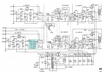
Would the highlighted addition to the left channel be a simple way to possibly improve the RIAA performance.
I have wondered about those capacitors for some time, but never got around to removing them.
Being relatively new to modifying this type of equipment, though used to working with high voltages. Where and of what value would the grid stopper resistors go/be?
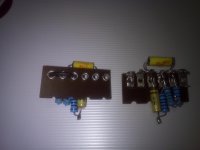
Attachments
After a lot of reading, I'm still no clearer on grid and screen stopper resistors values, the variation in values for any given valve type is quite large, and there doesn't seem to be any common reason why a particular value was chosen.
I did read on a lot of sites that using too high a value can cause compression and loss of top end, and also introduce noise. This is making me wonder if all amplifier designs require/benefit from having them?
I did read on a lot of sites that using too high a value can cause compression and loss of top end, and also introduce noise. This is making me wonder if all amplifier designs require/benefit from having them?
In addition to forming a low-pass RC filter with the Miller capacitance, thereby removing RF (particularly problematic at high-gain inputs which rectify AF) and preventing oscillation, the stoppers prevent arcing conditions. The goal is adding just enough impedance to prevent the arc from starting.
So, yes, all tube amplifier designs benefit from the stoppers.
So, yes, all tube amplifier designs benefit from the stoppers.
In addition to forming a low-pass RC filter with the Miller capacitance, thereby removing RF (particularly problematic at high-gain inputs which rectify AF) and preventing oscillation, the stoppers prevent arcing conditions. The goal is adding just enough impedance to prevent the arc from starting.
So, yes, all tube amplifier designs benefit from the stoppers.
How do you work out the correct impedance for any valve or situation, the information seems to vary wildly on this, and nearly always refer to guitar amps where they are not looking for hi-fi performance.
From retrovert's answer you can derive that the value depends on the triode properties. In early days it was common to use 8/gm kilo ohm. If your stage still oscillates with 10K grid stopper a higher value won't kill it.
Am I correct in thinking that the arcing problem mentioned is only likely to occur if the amp is driven hard? As my amplifier is hi-fi for home listening, as any more than 50% volume is likely to upset the neighbours, do I really need to be concerned? The amp has no other apparent problems that these resistors would cure.
My next question would be, if they are required / desirable, why are they not already in the design? I can't see it being a cost issue as they are cheap.
I am just trying to ascertain if they are a must have in all cases, some cases, if you amplifier wasn't designed with them, and seems to function okay without them.
Two issues exist: grid rectification and arcing. Well, more exist, but let's address just those.
The function of the grid stopper in a low-pass filter is more important to prevent grid-rectification of AM signals in the early, and thus high-gain, stages of the amplifier. Phono input, for example.
The grid stopper used downstream prevents arcing, and is a value of a few hundred Ω to maybe 1k Ω.
A 470 Ω resistor is generally considered to be the minimum value for anti-arcing purposes, with 1k Ω being superior. But, again, the grid stopper has multiple purposes.
The Q of either circuit, grid or screen, will affect the ability to support higher-frequency oscillation, and the higher frequencies sometimes manifests as lower frequency components. The biggest bang for the buck of the screen and grid resistors is suppressing any arcing potential.
The larger the grid stopper the greater the HF rolloff. But tetrodes and pentodes have lower Miller capacitance so one may likely use a much larger stopper resistor, perhaps as much as 47k Ω, without deleterious effects. Though I do not, of course, suggest doing this.
Beyond the low-pass issue, without a substantial value of at least 470 Ω any arc won't be prevented, and once started it won't quench until the B+ runs out. The trick is to add just enough impedance to prevent the arc from beginning and not enough to have any material effect on the circuit.
Here's a typical writeup which explains the basics: Error 404 - Not Found
I concur with that assessment, at least the cursory reading of it I performed while looking for a writeup so I wouldn't need to add one.
Am I correct in thinking that the arcing problem mentioned is only likely to occur if the amp is driven hard? As my amplifier is hi-fi for home listening, as any more than 50% volume is likely to upset the neighbours, do I really need to be concerned? The amp has no other apparent problems that these resistors would cure.
Yes, concern is warranted.
Arcing can happen from a number of reasons, and arcs can propagate through the tubes.
Here's some reading: http://tronola.com/Gillespie2544.pdf
My next question would be, if they are required / desirable, why are they not already in the design? I can't see it being a cost issue as they are cheap.
I am just trying to ascertain if they are a must have in all cases, some cases, if you amplifier wasn't designed with them, and seems to function okay without them.
Resistors are today inexpensive, but were far pricier back in the day. The cost to add a carbon-composite resistor, itself costing maybe thirty cents in today's money, might be equivalent of a dollar. The manufacturing cost to add a component is not merely the cost of the component; add in the labor to order, stock, and then install the component.
Consumer electronics has always omitted components to make a price point. So the fact that a component was eliminated does not mean it is not necessary, only that the sales would not be impacted by its omission.
Poor or sub-optimal design has many causes and one may not draw conclusions about the benefits of such designs. I would point to the number of rectifiers whose maximum current was exceeded, shortening the lifespan, or the number of output tubes driven past the datasheet's dissipation limits. The failures did not impact sales, and thus were not detrimental.
We, as rebuilders, have inexpensive and high-quality components not available to the original designer. Our labor is not multiplied by millions of units. So our options in installing components for better performance and longer life would not have been available to the original designers.
Thanks.
I had a few trailing characters on the URL when I converted it to a clickable URL.
- Status
- This old topic is closed. If you want to reopen this topic, contact a moderator using the "Report Post" button.
- Home
- Amplifiers
- Tubes / Valves
- Lafayette LA224B recap