A couple of days ago I had one of my mono-blocks go silent on me, and although I am trying to bring it back to life, it did get me thinking. What do I do if it’s dead?
I have ridiculously sensitive speakers and a box full of old Russian equivalents of ECC88 tubes. Could you build a power amp from these tubes? I know they are commonly used is pre-amps, but could you do it and get some good results? I think my speakers have a 95db sensitivity (6 ohm), so you could probably get away with pretty low power.
My current amps are beasts and I use the power to extend the base with DSP, but I’m sure I could manage with much less.
Well, taking a cue from one of PassLabs experiments … where Nelson lashed several hundred small signal FETs together as a homebrew push-pull power amplifier (which worked!), I suppose the answer is, “yah, sure, if you have a lot of sockets, and are willing to put a lot of power into the battalion of heaters!”.
One of the easiest topologies would be a low-voltage OTL implementation. With a bunch in parallel in the cathode-follower section. Split power supply could give pretty sweet active cathode load, too.
Anyway, Just saying,
GoatGuy ✓
One of the easiest topologies would be a low-voltage OTL implementation. With a bunch in parallel in the cathode-follower section. Split power supply could give pretty sweet active cathode load, too.
Anyway, Just saying,
GoatGuy ✓
Sure you can... It wouldn't make much power unless you're willing to parallel the tubes though.
Lingwendil has a thread about a 6SN7 flea power amp. You could adapt that to use 6N23P instead or design it from scratch. You could also design an amp using 6P1P and sell your 6N23P since they are going for ten times the price of a 6P1P the last I checked")
FWIW, I much prefer the sound quality of an overqualified amp. 1W from a 100W amp sounds much better than 1W from a 1W amp to my ears. That said, I've made some low power designs that sounded really great just not capable of high enough SPL to annoy the neighbours
Lingwendil has a thread about a 6SN7 flea power amp. You could adapt that to use 6N23P instead or design it from scratch. You could also design an amp using 6P1P and sell your 6N23P since they are going for ten times the price of a 6P1P the last I checked
FWIW, I much prefer the sound quality of an overqualified amp. 1W from a 100W amp sounds much better than 1W from a 1W amp to my ears. That said, I've made some low power designs that sounded really great just not capable of high enough SPL to annoy the neighbours
Last edited:
Impossible: no. Curious: absolutely.
I would start with design for headphones, with transformer or depending on 'a box full' an OTL. Full balanced should work too. It's just there is not so much power in it.
Connecting several in parallel is a challange on its own, but there is 'a box full'!
I would start with design for headphones, with transformer or depending on 'a box full' an OTL. Full balanced should work too. It's just there is not so much power in it.
Connecting several in parallel is a challange on its own, but there is 'a box full'!
A couple of days ago I had one of my mono-blocks go silent on me, and although I am trying to bring it back to life, it did get me thinking. What do I do if it’s dead?
I have ridiculously sensitive speakers and a box full of old Russian equivalents of ECC88 tubes. Could you build a power amp from these tubes? I know they are commonly used is pre-amps, but could you do it and get some good results? I think my speakers have a 95db sensitivity (6 ohm), so you could probably get away with pretty low power.
My current amps are beasts and I use the power to extend the base with DSP, but I’m sure I could manage with much less.
It's not only possible, for the SQ version (E88CC) the use as power amp even is specified, at Va = 200V. For PP, music, Raa = 10k with Po = 1.5W (at THD = 4%) so when your output transformer has a lower impedance, use a sufficient amount in parallel.
https://frank.pocnet.net/sheets/030/e/E88CC.pdf
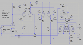
Similar "problem" here, a box full of 6n1p (6Н1П), what to do ? Well, build the All_6n1p_Amp, what else ... a total of 9 bottles for the stereo. Outputs are a full bottle each, parallel triode pairs, selected for similar parameters (my 6n1p's were all over the place). Direct coupled cathode followers allow the outputs to be driven into grid current. R2/R4 represents a 1 Meg pot, or actually two pots to get the DC balance.
Works better than anticipated, still ... a couple watts maybe.
Works better than anticipated, still ... a couple watts maybe.
Attachments
Last edited:
As usual power out limit is set by plate dissipation. Depending on which data sheet one reads total of both plates would be 2W. Referring to the attached they shew 0.5 to One Watt in Class A. That is consistent with the results I got running both triodes in a 6SN7 PP a while ago, all covered in Lingwendil's thread.
Attachments
They are also quite usable to make single-bit DACs ( https://www.diyaudio.com/forums/dig...c-linear-audio-volume-13-a-9.html#post5856267 ).
Similar "problem" here, a box full of 6n1p (6Н1П), what to do ? Well, build the All_6n1p_Amp, what else ... a total of 9 bottles for the stereo
Nice…
Couple of design thoughts.
The wiper of that R₂ R₄ pair ought to have a 10 µF 50 V capacitor running to ground. I agree, the resistor-divider combo is making a variable negative bias supply. However, without that cap, the combined resistance is a substantatial fraction of the reactance of the U₆ and U₇ anode loads. Wiggly stuff shouldn't, but could end up on the C- rail.
R₁₆ and R₁₃ are designated at value-precision that isn't warranted. Commonplace resistors would do just fine. R₁₃ = 100 Ω, R₁₆ = 4.7 kΩ or 5.1 kΩ or even 5.6 kΩ.
C₄ is 10× larger than it needs to be. Pole at 0.71 Hz. 7 Hz is just fine… so 47 µF.
Grids of U₆ and U₇ are in grid-leak biasing mode! Kind of cool. What floating voltage do they run at? Funny thing though, I don't think that it matters. Tying them to ground, bypassing C₃ entirely is going to result in less feed-in wiggle on U₇. Can't imagine why the designer would want it… just saying.
That's about all.
Without even a single mod, I bet it works pretty well.
With the huge surplus of bottles, it wouldn't be hard to use 2⊕2 or 3⊕3 bottles on each L+R channel's PP output, to further kick up the power. The cathode-followers preceding the output bottles makes that a trivial-to-do idea. Now, getting bulbs to be relatively well matched … is another kettle of fish entire.
Just saying,
GoatGuy ✓
Sweet, it sounds like it might be worth looking into then. But first priority will have to be resurrecting my regular amp. It’s kind of embarrassing, but since all of my electronics tools are either in storage or has died themselves, I’m flying blind here.
Anyhoo, thank you for the great feedback. I should know within a day or two where it’s heading...
Anyhoo, thank you for the great feedback. I should know within a day or two where it’s heading...
I'm in gothenburg too .....Sweet, it sounds like it might be worth looking into then. But first priority will have to be resurrecting my regular amp. It’s kind of embarrassing, but since all of my electronics tools are either in storage or has died themselves, I’m flying blind here.
Anyhoo, thank you for the great feedback. I should know within a day or two where it’s heading...
What kind of amp is it ?
It's a Hypex nCore. Up until now it's been regular like clockwork.I'm in gothenburg too ..... What kind of amp is it ?
Well, it doesn't appear to be the fuse...
So, I guess I'm officially looking for ideas now. I suppose trading some of the tubes for proper power tubes would be an option? I really wouldn't mind a super simple push-pull amp with a single output tube and transformer. I do like simple... Not really what I was asking for initially, just saying I'm open to pretty much anything at this point.Refer to the results I obtained running several different dual triode amps in Class A PP on Ling's thread. 6SN7 Push Pull Flea Amplifier Project.
6SN7 One Watt, 6BL7 or 6BX7 3 Watts & 5998 10 Watts, all no FB. Lots of actual results measurements listed & Harmonics results plotted.
6SN7 One Watt, 6BL7 or 6BX7 3 Watts & 5998 10 Watts, all no FB. Lots of actual results measurements listed & Harmonics results plotted.
Well, it doesn't appear to be the fuse…
First, nice avatar. I got all my kids posters of the Swedish Chef for their dorm rooms, for college. Love it.
Second, in my “critique of the suggested amplifier”, last night - oh, around 2:30 AM - I got to thinking … and realized that one aspect of my opinion was likely wrong:
Tying them to ground, bypassing C₃ entirely is going to result in less feed-in wiggle on U₇. Can't imagine why the designer would want it… just saying.
Turns out that since the first stage is not DC decoupled (i.e. no DC blocking capacitor) from the second pair of valves ("the symmetric inverter section"), that the cathode is going to run “up there” voltage wise. To get a proper bias on the grids still allowing current flow requires some sort of positive bias. I guess the grid-leak approach will do the job.
Just seems a big iffy to me. Iffy from the point of view that as the pair of tubes in the inverter age, it is not obvious that the grid-leak will do what's needed, especially with respect to the 2 tubes as a pair.
Anyway.
Offloading my early AM thunks.
Bork, bork, bork!!!
Just saying,
GoatGuy ✓
Last edited:
If you have very sensible speakers this might be something :Well, it doesn't appear to be the fuse...
So, I guess I'm officially looking for ideas now.
I suppose trading some of the tubes for proper power tubes would be an option?
I really wouldn't mind a super simple push-pull amp with a single output tube and transformer. I do like simple...
Not really what I was asking for initially, just saying I'm open to pretty much anything at this point.
https://www.tradera.com/item/170613/363298757/aga-9016-rorforstarkare-
it's 2+2w , schematics is available and it's lacking RIAA. But it's cheap
And it's already in sweden !!Haha, that is truly vintage.
My speakers are quite sensitive, but not at all sensible.
I honestly don't know exactly how much juice I need. I've had more power than I ever needed and ran linqvitz transform to extend the bass. (Rocking 15" drivers...)
I would love to build a PP amp with transformers both on the input and output. I really love the concept... but I would need some serious hand holding to figure out exactly what components to use and how to get everything playing nice together. It seems the design would be perfect for a couple of monoblocks. Only one power supply in each block and a lot of iron.
I haven't been active in DIY for a couple of years now and I have issues with my memory. So I can't remember much of what I used to take for granted. Suffice it to say simple is key...
I'm still reeling from the concept of suddenly facing a new build.
The venerable 2A3 power triode has Cag=16.5 pF and an E88CC (and equivalent) has Cag between 1.2 and 1.6 pF so 10 E88CC would have to be paralleled for the same Cag as the 2A3. With fixed bias and in PP, the 10 E88CC (at Va=200V) could deliver 15W at THD=4% and the 2A3 (at Va=300V), 15W at THD=3%. The major difference would be the drive requirements (easier for the E88C) and aesthetics (brightly glowing filament vs dim cathodes).
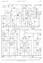
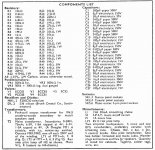
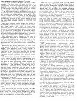
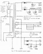
Practical Wireless published a power amplifier design based on ECC83 + PCC88. The author declares 2.5W at 1% distortion (1 KHz) with 10 ohm load. That's not bad at all. The design also featured a unconventional preamp section depicted in the bottom half of the schematic.
Attachments
- Status
- This old topic is closed. If you want to reopen this topic, contact a moderator using the "Report Post" button.
- Home
- Amplifiers
- Tubes / Valves
- ECC88 for power amp?