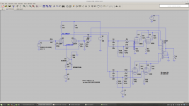
I am trying to redesign an amp that was built with 6550 output stages. It uses an op-amp (OP453) to drive the output valves directly this gives 120W rms per channel.
Works fine but something of a cheat! So I am trying to replace the driver stage with valves without inceasing distortion too much. This is an early schematic. It a pretty standard design.
First tried the dominate pole of the amp directly across U1 plate to supply, and U2 plate to supply. This did not work at all well causing instability on the peaks of the sine wave. I think the impedance changes a lot here shifting the pole around.
I tried the dominate pole across the plates between U1 and U2. This was much better, but a 10KHz sinewave shows heavy slew rate limiting. 1KHz was fine and gave good THD.
The third attempt is placing the dominant pole between grids of U1 and U2 as shown in schematic. This does seem to work. Is this a known method or is something being overlooked - is there another place that could be used? There is a small current flow now in R24 of 35uA at 15V sinewave 10KHz but I hope this will not affect a first stage too much.
What would be a good first stage? I need a gain of about 15x? It’s not in the NF loop so needs to be low distortion. 15V pk sinewave provides full output of 42v pk into 8R. I could run this heater on DC.
Attachments
That 35uA is the grid leak current. You should put a 500K or so resistor form Grid to ground. That should take care of that current. The way it is now, I think the grid current is flowing into the source signal generator. If you have a source that block that current, bad thing can happen.There is a small current flow now in R24 of 35uA at 15V sinewave 10KHz but I hope this will not affect a first stage too much.
Have you consider using a 100pf instead of 33pf NFB compensation cap instead of putting in that CR divider NFB path directly from the input.
Yep will look at 12AU7 in simulation. Sorry the 35uA refers to the current flowing through C1 R25 not grid leak. It still very small so should not affect first stage. Understand will need DC path to ground on grid.
Could you sketch what you mean by moving the 100pf as I did not quite understand. That would be great.
Could you sketch what you mean by moving the 100pf as I did not quite understand. That would be great.
Another thing to look at -and this makes life for the driver harder- is the maximum value of the grid leak resistors of the 6550's. The 470k for R17-20 you have now are 10x higher value than the datasheet listed maximum: fixed bias 0.05M, cathode bias 0.1M. If you don't run them too hot, you may get away with 0.1M but I wouldn't go higher than that. You need a strong driver and enough gain. I use two stages for amps like this: ltp phase splitter, followed by a driver stage. Two 6SN7's per channel work well.
If you direct couple the input stage to LTP driver you could eliminate the negative supply. That's the way Eico did it on the HF-87 & 89.
That's quite interesting with the NF on the first stage and DC coupled! Could be worth a simulation. Wonder why NF is from both 4R and 16R tap.
The negative supply can share with the same transformer tap that generates the negative bias for the 6550. I need 4ma per channel. Must made sure it does collapse too quickly when turning off the amp (or there will be a thump).
Dropping grid leak resistors to 100k drops open loop gain by 1.5dB OK. Need to increase tail current to 6ma and 380v supply to give ample drive from LTP (dissipation OK). So will make this change.
Op-amp circuit had DC drive to 6550 through 10k so was no issue before. Thanks for spotting running them at 40ma per tube.
Last edited:
As Parafeed813 said:
I agree: The feature that can potentially smoke all of the 6550 tubes is this:
You are using fixed bias for each tube that was 470k in the first schematic, but now is 100k in the latest schematic.
The 6550 is rated for no more than 50k grid resistor from the fixed bias supply. Ask me how I know. Well, I am not the only one who has heard a 6550 amp sound good, then distort suddenly, then look at the Red Plate(s) and have to turn the amp off (immediately). Lesson learned.
Some 6550 tubes are more robust than others. And some 6550 tubes are more busted than others.
If you really want to keep those 100k grid resistors, use EL34 tubes, they are much more forgiving of that resistance. Fixed (and Fixed adjustable) bias really can be hard on tubes if you violate the grid resistor spec.
Last edited:

I had the same thing happen on an EL34. That could be a sudden short in the valve - they can glow quite brightly until the fuse hopefully blows!
I understand that with high value resistors there is a good chance of thermal runaway. The Marshall guitar amps tend to use a value of 150k. If I go down to 47k I will have to add a buffer. Understand I am not using the recommendations of the data sheet. The op-amp version of this amp had 120W rms per channel. However I may well build a smaller version of this with just a pair of 6550's (and a different transformer) as its for upstairs. In that case the driver will provide enough power for a single pair with 47k. The other thing I could check is the grid leak current on all 8 valves currently.
Last edited:
Hedges used a similar LTP as the front end/driver as did Morgan Jones in his Crystal Palace amp and there's similar "differential input" design for the Dynaco ST70 in a Glass audio article that might be worth a look at.
Glad to see you have a cap across the zener on your CCS in V2.
Andy.
Glad to see you have a cap across the zener on your CCS in V2.
Andy.
I had a KT-120 arc during a loud music passage on my PPP mono-blocks. My cat was sitting next to the amp at the time; you should have seen him jump. ;>) The amp kept on playing after the arc cleared like nothing had happened. The grids of the output tubes are connected to an IT with a DCR to ground of 330R and the four triode strapped output tubes are configured as an LTP with a single CCS tail. I was surprised that the CCS survived intact. SS components can be so delicate. Apparently by limiting the current it minimized any damage.
baudouin0,
It is about several factors:
Pentode mode, or Ultra Linear mode, or Triode mode.
Quiescent:
Plate voltage, screen voltage.
Plate current, screen current.
Control Grid Resistance.
Ambient temperature, Air Flow around the tubes
Signal present:
Signal amplitude
How well the signal excursion passes under (less than) the set of curves maximums, such as plate dissipation beyond the spec, where, and what portion of the excursion, time percentage of violation.
etc.
Reminder: some tubes of a particular type are robust, some others of the same type are easily busted.
Your mileage may vary.
Last edited:
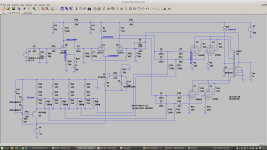
OK had a long think about this.
Sticking with the 6550 in ultra-linear mode. So added irf730 buffers to drive 6550 properly. Problem was capacitance on 6550 grids was adding a pole and affecting stability. Can now use 12AX7 in LTP with more gain gives enough NFB at HF. 12AT7 works OK in LTP but with reduced NFB and don't need power handling now. Don't need balance pot in LTP has constant current source means output AC on plates will always be the same even if DC is different.
The dominate pole C1 R25 is correct without ground - it shorts the two grid together reducing gain. The impedance here is constant and does not affect slew rate so 10kHz goes through full power.
Reduced the impedance on grids U1 U2 to reduce miller effect again adding unwanted pole. Added bootstrap follower on input stage - reduced second harmonic distortion and reduces impedance into U1 - works a treat. All the mosfets could be cathode followers 12AU7 but I think I would need to run these on elevated heater.
Happy with the distortion (40v into 8R shown).
Last edited:
- Status
- This old topic is closed. If you want to reopen this topic, contact a moderator using the "Report Post" button.
- Home
- Amplifiers
- Tubes / Valves
- Neagtive feedback - circuit topology