I definitely did not know that.No driver can push the grid vary far positive through a cap. That's why the Tubelab board uses a mosfet for driving the grid directly.
It is not clear whether your driver circuit can swing enough drive voltage WITHOUT any 6L6 grid to drive, that's why I asked. The drive gets clipped with the tube in place. Does it still get clipped in the same place without the output tube? If so, you need to fix that before worrying about the output stage.
With the 6L6's pulled, feedback in the "off" position, and the PI adjusted to max clean, I got ~60 V peak on the scope and 41.1 V rms on the meter at pin 5 of the tube sockets. Balance appears pretty good too as the pull tube was at 40.8 V.
Your terminology and schematic looks like that this may be for a guitar amp application? If that's the case you don't want to hit the 6L6's hard enough to keep it in the serious positive grid zone because long term overdrive (crank it to 11, connect up a pedal board full of overdrive boxes, and beat on it for an hour or so) can fry a grid.
Yup, guitar. That's why I'm kind of perplexed because this phase inverter and output stage are standard in the guitar world...it's basically a Bassman 5F6-A but I increased the Rscreen to protect the tubes if overdriven, and I adjusted the PI to be center biased and to have a touch more gain to compensate for the extra load from the master volume pot. That's a 60W amp with 5881's, a tube rectifier, and approximately the same voltages.
That's interesting about the grids. Again, this is basically "the standard" guitar power amp design, how have guitar amps gotten by with it for so long, and is there anything to do to protect them?
Did you actually measure such a standard guitar amp yourself?
Two output tubes is often called 50W and 4 makes 100.
Reality can be quite different.
Long ago I had a '100W' 4x EL34 anniversary Marshall on my bench that clipped at barely 80W sinewave.
Tiny output transformer compared to my old plexy super bass which also had 100V more anode voltage. Decent EL34s produce over 120W before clipping in that one.
(UK made Mullards even more).
Both amps are called 100W.
Don't worry about the grids when they are cap coupled they won't melt. Especially when you drive them with a whimpy ECC83 (12ax7). Hardly any power in them.
bla bla bla
I just understood your signature!
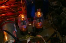
That's insane! What happened when the tube arc'd? I'm imagining fire and brimstone, lol.
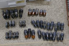
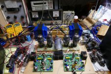
This was one of many test runs with the Tubelab driver board feeding several different tubes from metal 6V6's and 6V6GT's to some big TV sweep tubes. I happened to have a box full of assorted 6L6 types with about a dozen 6L6GA's, so I picked two pairs of crusty looking old tubes, stuck a pair in each channel and proceeded to find their limits.
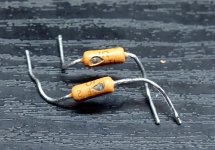
I was somewhere north of 500 volts and 113 watts, when there was a loud snap and one channel went dead. The only casualty was a blown 1 ohm cathode resistor. I replaced it and cranked it up again. It lived for about a minute at 105 watts, but when I pushed it to 110 watts the other channel blew a resistor. All 4 tubes are still alive and working.
That's when I decided to dial it down and test the metal 6V6's. I have 8 new ones that I'm saving for MetalicAmp. A guitar amp that's all tube....no glass. My rendition of what Leo could have built in the late 1940's, using only parts that were available at the time.
Attachments
Did you actually measure such a standard guitar amp yourself?
Two output tubes is often called 50W and 4 makes 100.
Reality can be quite different.
Long ago I had a '100W' 4x EL34 anniversary Marshall on my bench that clipped at barely 80W sinewave.
Tiny output transformer compared to my old plexy super bass which also had 100V more anode voltage. Decent EL34s produce over 120W before clipping in that one.
(UK made Mullards even more).
Both amps are called 100W.
No I haven't. And I know that manufacturer's fib a bit when it comes to power output, but I didn't think it would be by that much. And I guess I'm just bummed cause I thought I knew what I was doing, and my calculations were showing 55W or so, but I'm not even ballpark for that.
I was somewhere north of 500 volts and 113 watts, when there was a loud snap and one channel went dead. The only casualty was a blown 1 ohm cathode resistor. I replaced it and cranked it up again. It lived for about a minute at 105 watts, but when I pushed it to 110 watts the other channel blew a resistor. All 4 tubes are still alive and working.
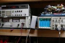
That's pretty damn cool, especially since it doesn't even look like those resistors had time to burn...they just blew a hole. Out of curiosity, what is that device above your DC power supply. It looks cool.
liquidair,
Do not forget the non-trivial loss of the output transformer.
Example Output Transformer:
Primary:
4.2k p-p
210 Ohms DCR
Secondary:
8 Ohms
0.4 Ohms DCR
Such a transformer will have 0.5 dB loss in the primary.
Such a transformer will have 0.5 dB loss in the secondary.
That is a total loss of 1 dB. That is 1/(1.25) of the power from the 6L6 tubes.
50 Watts/1.25 = 40 Watts
Could that be part of the cause of the lower power than what you are expecting?
Could that be part of the cause of the lower power than what you are expecting?
I definitely did not consider that at all! But even if we are expecting 40W, I'm still off by 25%, I'd likely accept 40W.
For future reference, what is the method to use so the results are accurate? Like say I set out to build another 50W amp, how close can I expect to get via calculation?
I'm going to try other tubes tomorrow, I have a pair of 5881s and EL34s. What will happen with the 5881s? Won't they be easier to drive?
Especially when you drive them with a whimpy ECC83 (12ax7). Hardly any power in them.
Yup, all the drive of a wet noodle.

jeff
For a first order approximation of transformer insertion loss:
Measure the DCRs of your primary and of the secondary.
Compare those DCRs versus the rated primary and secondary impedances.
Consider that the DCR is in series with the real impedance of the winding (DCR, which may, or may not, be included in the manufacturer's impedance ratings).
Consider that there is a voltage loss according to the DCR in series with the winding impedance.
Calculate that voltage loss according to the DCR and rated impedance, it is a simple voltage divider.
Power is according to voltage squared. A voltage loss that outputs 89% of the original is a 1 dB loss. It is 1/1.25 of the original power.
The power loss includes that of the primary and that of the secondary.
The impedance ratio is according to the square of the turns ratio.
A 5k primary and 8 Ohm secondary has a 25:1 turns ratio.
25 squared x 8 = 5000
Some careful techniques will give the actual turns ratio.
Incorrect techniques do not take into account resonances, inductance, distributed capacitance, and DCRs.
I will not go into that at this time.
At mid frequencies, impedance is according to the DCR, the square of the turns ratio, and the impedance of the load on the secondary (or if looking backwards, the impedance that drives the primary).
Okay, so you sort of lost me on how to calculate this. I measured the DCR pri as 90 ohms, and sec 8 ohm tap as .39 ohms.
Looking at the primary which is 4200, we would get out 97.902V if we put in 100V. Then here's where I get confused on how to get to the db figures. To calculate the power loss, which voltage and which impedance do we use?
The good news is that I tried some EL-34's and got 40W out today. And whilst playing through the unit with the meter attached to the load, a couple of times I saw 26V pop up a few times so we got 80W peak. We can count that as somewhat of a victory, no?
Out of curiosity, what is that device above your DC power supply
It is a Hewlett Packard 8903A audio analyzer from the 1980's. It measures THD, audio voltage, power and can make relative (dB) measurements at any frequency from 20 Hz to 100 KHz. It also has an ultra low distortion audio signal generator. With a PC interface and some software, or several minutes of button pushing it can measure frequency response too. It is measuring 112.7 "watts into 8 ohms" in that picture.
it doesn't even look like those resistors had time to burn...they just blew a hole.
That ancient history HP power supply has 1000uF of output capacitance built inside. That stores enough energy to really bow stuff up. In this case the tube arc dumped all of that energy into the resistor causing a chunk of it to vanish. Some dumm blonde arithmetic led to a tube arc in a much bigger tube that did not have a resistor. The first tube just shattered......so the dummy sticks in another tube and tries again. That one exploded scattering glass all over the room. Some bad math convinced me to apply 300 watts to a 24 watt tube instead of 30 watts.....BANG happened.
liquid air,
You got the primary voltage loss factor right. 4200/4290 = 0.97902 of the original voltage. The secondary voltage loss factor is 8/8.39 = 0.95352
The voltage loss factors are multiplicative.
0.97902 x 0.95352 = 0.93352
Power goes as V squared
0.93352 V squared = 0.87146 power loss factor
50 Watts x 0.87416 = 43.573 Watts
That is pretty close to what you got with EL34 tubes.
I will call the total of the primary and secondary voltage loss factor 0.9335.
20 x Log voltage ratio = dB
20 x Log 0.9335 = -0.597 dB (- 0.6 dB)
I will call the total of the primary and secondary power loss factor 0.8715.
10 x Log power ratio = dB
10 x Log 0.8715 = -0.597 dB (- 0.6 dB)
Your transformer loss is about -0.6 dB, not including any core loss and leakage inductance loss. By the way, the instantaneous power at the crest of a sine wave is 2 X the rms power of the sine wave. 40 Wrms = 80W @ crest (peak). Other wave shapes, like square waves, and music have different ratios. Square waves have a fixed ratio, music is dynamic and so no fixed ratios.
===
Tubelab_com,
Those who use bench-top power supplies and DC current probes to measure the inrush current of some new engineering design, are often surprised when their new design has a large capacitor across its voltage input. They set the power supply current limit to 3A (with the current sense resistor that is Before the power supply output capacitor). Then they ask why the 30A current probe went into overload protection mode.
Most everybody that had access to a DC current probe (and yes me) has discovered the cap that was inside the power supply.
One cap said to the other cap, lets cause a very large inrush current, and make the current probe overload trip. Ahhhh!
How to make a push pull guitar amp meet its output power spec:
Drive it into Full clipping.
Square waves Have power.
Sounds just like some songs require it to sound.
Just do not try that in a small, quiet jazz club.
In fact, there's twice as much power in a square wave as in a sine wave of the same peak amplitude, because the RMS value of the sine is (peak voltage/square root of 2) , while the RMS value of a square wave is just the peak voltage.Square waves Have power.
That means with a hypothetical amp with zero output impedance and a perfectly regulated power supply, the output power would double when you go from clean sine wave to fully flat-topped square wave.
And that in turn means the power contained in all the harmonics would equal the power contained in the fundamental (the sinewave.)
Using the usual definition of total harmonic distortion (power in all harmonics / power in fundamental), that means you have achieved 100% THD.
")
While the last lingering survivors of the solid-state Hi-Fi era fight over the merits of amplifiers with 0.0005% THD, the gods of rock guitar use distortion pedals and vast amounts of overdrive in the attempt to get to 100% THD.
-Gnobuddy
Depending on how willing you are to experiment, you could still make that happy ending happen......this thread *almost* had a happy ending...
Tubelab (George) laid it out: you'll need a pair of N-channel MOSFETs, a relatively low-voltage positive supply rail (just a few mA needed, and maybe only +15 volts), and a negative supply rail of about twice the bias voltage needed for the 6L6 output tubes.
The MOSFETs go between your phase splitter and the output tubes, in source-follower mode, directly coupled to the 6L6 control grids. That lets you drive your 6L6s into positive grid voltage territory, and I think you'll get the 50 watts output power you were looking for without too much trouble.
Ever since I read about George's ability to get extraordinary amounts of power out of mundane tubes using class AB2, I've wanted to build a guitar amp along these lines, with MOSFET source-followers driving the output devices. I haven't got around to it yet. Maybe you'll beat me to it.
-Gnobuddy
Do you have a 12AT7 to try in place of the 12AX7? You almost have a Fender Twin circuit there. They use a 12AT7 and slightly different resistor values but you are close. Maybe just parallel the 1K cathode resistor with another 1K to get 500 ohms there for a down a dirty test. It is a guitar amp after all.
Wrong.See attached for the schematic.
Thank you for the vote of confidence, but doesn't your Tubelab specs suggest something is wrong with mine? Ignoring your UL connection for a sec, we can assume an effective 350V B+ into 1.25k should get around 98W peak, or 49W. Factor in the UL being somewhere in between triode and pentode operation and 40W sounds right.
Whereas mine would be an effective 370V or so into 1.05k, which would be 130W peak, or 65W. So 30W seems pretty bad, no?
Sorry.
You are optimistically/naively supposing tubes have no or very little saturation voltage and can pass as much current as load demands ... not so at the Real World.
If +V drops to +408V and we lose 8V (just to round things up) because of primary DCR (which will be between 30 and 50 ohm, not catastrophic but can´t be ignored either) and we consider 60V saturation voltage at high current levels (just look at the datasheet curves), we are left with 340V peak; a significative difference with your assumed 370V to begin with.
And 340V peak into 1050 ohm would require 340mA peak ... a tall order for almost any 6L6.
Think 250/280mA peak and we are talking, at least with run of the mill 6L6 .
Use that new Math and you´ll see it´s quite close to your actual results.
A very common mistake in modern designers weaned on Silicon devices is to treat tubes as SS devices ... nothing further from the truth.
Here lowering load impedance does not increase power output as in SS, quite the contrary, because, repeat with me kids:
"Tubes are current limited devices"
There´s a reason in the old days 6L6 were often specified 6600 ohm and even higher plate loads ... there is a reason for that.
Absolute worst case, you don´t get 50W either, but tubes do not suffer, do not get worn fast trying to supply current they can not.
Designing graphically (the old way) just using datasheet curves will tell you exactly the same.
Yes, driving tubes in Class AB2, either using driver transformers (the old way) or turning them into some kind of Darlingtons (and I am only half kidding here) which is the ultramodern way by driving grids positive and injecting current there is one way of getting more peak current ... but then that´s an entirely different game.
discovered the cap that was inside the power supply.
That particular power supply is an old 60 Hz "switcher," basically a triac "light dimmer' on the input side of a LARGE power transformer which feeds a bridge and a CLC filter with 1000 uF of cap. There is a control circuit wrapped around it all, but the loop corner is about 1 Hz. Turn up the voltage all the way, set the current limiter to a low value, apply short, explosion happens, then after a short delay the supply groans as the throttle is hammered, and the bench lights dim, then after a few hundred milliseconds, the limiter kicks in and the throttle is pulled back. By then the circuit you were testing is gone!
It was given to me for free, but had been left outside in the Florida rain for an unknown amount of time. I opened it up, cleaned out the crud and rust, and it worked. You must understand how these work, respect their abilities and use them only when nothing else will do.....After turning a few internal adjustments up all the way, I can get 650 volts at 1.7 amps out of it which will power 4 X 35LR6 sweep tubes to 525 watts at the edge of clipping.....and a dull red glow.
and we consider 60V saturation voltage at high current levels......would require 340mA peak ... a tall order for almost any 6L6.......I tried some EL-34's and got 40W out today.
The peak current is related to how much can be emitted by the cathode. Look at the cathode size in the 6L6, then compare the cathode in the EL34......it's about twice as big, and therefore can pass more current for a given tube drop......Got some 6550's or KT88's?
Remember that bigger cathodes need bigger heaters, which eat more current. Make sure that the heater winding in your power transformer can safely power those EL34's or KT88's before you leave them in there for more that a few minutes.
Yes, driving tubes in Class AB2, either using driver transformers (the old way) or turning them into some kind of Darlingtons (and I am only half kidding here)
I prefer the use of mosfet source followers to drive tube grids. They are the best component for that job, but I have never used a mosfet in a tube amp in anything but a follower or a CCS. They are not linear enough for voltage gain.......still don't want a mosfet in there? Use a tube with lots of Gm and a good deal of current handling ability. A small pentode, or a triode like the 5687 works good, but not as good as a $2 mosfet.
Some tubes respond well to AB2 operation, others don't respond, while some others just don't like it. All of the 6L6 types DO like it, but they respond so well that it's easy to push them too far......100 watts from a pair on 500 volts into 3300 ohms IS too far.
TV sweep tubes generally don't like it, but some of them have peak current ratings in the 1 AMP and over range, so it's not necessary.
- Status
- This old topic is closed. If you want to reopen this topic, contact a moderator using the "Report Post" button.
- Home
- Amplifiers
- Tubes / Valves
- Can't get full power