Hello everyone.
I am in the process of designing my second tube amp, ever.. And I could use a sanity check on this design before i make my PCB. Usually this forum is great at pointing out, that what i am doing isnt the greatest ideer")
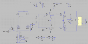
At max output I have 24.5W at 0.55% THD with 8dB feedback.
The voltages for the output tube is taken from the datasheet.
http://nekhbet.com/STC807.pdf
The output transformers i have are from an eico st70, that is why it isnt coupled in ultra linear on my schematic. I use a model for a hammond 1620, which should be fairly close I hope
I am in the process of designing my second tube amp, ever.. And I could use a sanity check on this design before i make my PCB. Usually this forum is great at pointing out, that what i am doing isnt the greatest ideer
At max output I have 24.5W at 0.55% THD with 8dB feedback.
The voltages for the output tube is taken from the datasheet.
http://nekhbet.com/STC807.pdf
The output transformers i have are from an eico st70, that is why it isnt coupled in ultra linear on my schematic. I use a model for a hammond 1620, which should be fairly close I hope
Attachments
Last edited:
The gate capacitance of the MOSFET's are 400pf and you will need to check that the input stage can reasonably drive this 400pf. I have not done a calculation but this is probably going to be a issue at high freuency.
The MOSFET drive will support AB2 so its possible to consider Triode connection. The Triode curves show that the 807 is reasonably linear at +7.5 volts on the g1 so this may be a better connection that pentode especially if your transformer does not provide ultra linear taps.
The MOSFET drive will support AB2 so its possible to consider Triode connection. The Triode curves show that the 807 is reasonably linear at +7.5 volts on the g1 so this may be a better connection that pentode especially if your transformer does not provide ultra linear taps.
Thank you
I am so used to using my mosfets in circuits with a beefy driver, that I forgot the input capacitance.. And the impedance of a 400pF cap, at 20kHz are close to 20kOhm..
so it will properly be a problem, even though the input capacitance is lower then the 400pF since it is a source follower.
I really need some kind of book about tube amps I am still a bit confused about all these modes. But I will look at triode coupled with the possibility of AB2.
Again, thanks this was exactly the kind of feedback I was looking for.
Ab2 Triode will give more power that ab1 Triode but I think that the 807 g2 max voltage is only 300 volts so this may be an issue. There is a thread on this site covering a AB2 triode design with EL84 driven by an op amp ....worth a look.
You could consider the 6n1p for the first stage, its output impedance is a lot lower with more current, but its gain is about half so getting 8 Db of feedback will be a challenge
You could consider the 6n1p for the first stage, its output impedance is a lot lower with more current, but its gain is about half so getting 8 Db of feedback will be a challenge
Will look at that thread. There is also the question of needing more power. I dont really need more than 25W, but that is no reason not to read up on it anyway.
I have played with 6n1p, but as you say, then i cant have any feedback. I have however considered going no global feedback.. My solid state amps are ngfb, and i quite like them.
But there is no reason to use a power mosfet that is able to deliver severel amps in this position. I mainly used it, because I have some of them. But a quick glance at mouser showed that I should be able to find a suitable replacement with sub 100pF input capacitance. And that will solve the drive problem.
I have also considered just using a 6n1p as a cathode follower instead of a fet. Intuitive it just seems better to use a fet in that position. Maybe I should just make 2 boards and compare them. All these options.... I love it, but sometimes it would be nice with a simpler hobby
The gate capacitance of the MOSFET's are 400pf and you will need to check that the input stage can reasonably drive this 400pf. I have not done a calculation but this is probably going to be a issue at high freuency.
MOSFETs are connected as source follower, therefore the actual gate capacitance that 6N2P-EVs "see" is just a few pF.
Pentode mode outputs and no negative feedback taken from the output stage will make the damping factor less than unity (<1).
But if you are going to use negative feedback, it will require careful attention to the gain and phase of the amp versus frequency, and choice of the output transformers.
But if you are going to use negative feedback, it will require careful attention to the gain and phase of the amp versus frequency, and choice of the output transformers.
There is GNFB (from output to U4) in the schematic but not very clearly drawn.
Usually smaller than, say 16 dB of GNFB is easy to manage.
Essentially more power with AB2.
Usually smaller than, say 16 dB of GNFB is easy to manage.
The 6n2 will drive the 807s adequately, why bother with more components?
Essentially more power with AB2.
artosalo,
In post #5, he said he was considering having no global negative feedback.
I pointed out what would happen to the damping factor.
(I did not even talk about increased distortion)
Many threads on this forum of various OPs asks how to tame
amps that are struggling because of global negative feedback problems.
Was there a mention of what output transformers were going to be used by this poster that I missed?
Just a couple of observations.
'Easy to manage' is one person's happiness, but another less knowledgeable person's
trouble.
Last edited:
AB2 will significantly increase the distortion.There is GNFB (from output to U4) in the schematic but not very clearly drawn.
Usually smaller than, say 16 dB of GNFB is easy to manage.
Essentially more power with AB2.
In post #5, he said he was considering having no global negative feedback.
Sorry, I did not notice that. Of course pentode output amplifier needs some sort of NFB, otherwise the audio performance is similar to tube radios from fifties.
AB2 will significantly increase the distortion.
No, if well done.
...but the 6.8k grid stoppers will cause lots of clipping...
Sorry, I didn't notice this either. Not 6k8 grid stoppers for AB2 drive, preferably 68 or 6.8 ohms.
First off, I have no plan of going into ab2 territory, I dont believe that i really need more than 25W.
The reason I put the source followers on, are simply because I want to affect the gain in the ltp as little as possible. And well... I would do something similar on a ss-amp.
About the talk of feedback. I know that my dampning factor will be quite low without feedback, but I am curious to try, simply to hear the effect.
And distortion wise, in my simulations it doesnt get that bad, when i remove the feedback, if I get around 1.3% thd. which isnt that bad.
So is the reason that you guys say that i need gnfb, distortion, dampning factor or something else?
btw. at the moment it runs with approximate 8dB feedback.
And I am going to use some opt from an eico st70.
And thank you all for your inputs it is greatly appreciated.
The reason I put the source followers on, are simply because I want to affect the gain in the ltp as little as possible. And well... I would do something similar on a ss-amp.
About the talk of feedback. I know that my dampning factor will be quite low without feedback, but I am curious to try, simply to hear the effect.
And distortion wise, in my simulations it doesnt get that bad, when i remove the feedback, if I get around 1.3% thd. which isnt that bad.
So is the reason that you guys say that i need gnfb, distortion, dampning factor or something else?
btw. at the moment it runs with approximate 8dB feedback.
And I am going to use some opt from an eico st70.
And thank you all for your inputs
it is greatly appreciated.250V for MOSFETs is too high, you will fry control grids on transients, you need to limit their current on peaks. Better increase the negative voltage, to avoid audible clipping of negative peaks.
Obviously, grid stoppers have too high for A2 values. You may use jumpers instead of resistors on PCB if find later that they are not needed.
Add some dominant pole compensation just in case if you will need it.
Obviously, grid stoppers have too high for A2 values. You may use jumpers instead of resistors on PCB if find later that they are not needed.
Add some dominant pole compensation just in case if you will need it.
Don't do that, trust me on this. You might be able to get away with PP pentodes without any NFB if you're using something like the 6V6 or a TV HD type like the 6BQ6. Without gNFB, the 6L6-oids will sound really bad, as this type likes to make higher order harmonics. Even though the STC Report has THD= 1.8%, that's a bit misleading. That's what I measured, however, the residual after nulling out the fundamental looked like a near perfect sawtooth at three times the frequency -- lots of H5 and higher. That leads to a sonic effect as annoying as fingernails on a blackboard. With the 6BQ6, that residual looked like a slightly distorted sinewave: mostly H3 with a trace of H5. Even though the amplitude was higher (THD= 3.0%) the sound was mainly overly "aggressive", but not nasty. Add just enough gNFB to take the "edge" off.I have played with 6n1p, but as you say, then i cant have any feedback. I have however considered going no global feedback.. My solid state amps are ngfb, and i quite like them.
The 6L6-oids need the assistance of NFB in order to sound their best.
But there is no reason to use a power mosfet that is able to deliver severel amps in this position. I mainly used it, because I have some of them. But a quick glance at mouser showed that I should be able to find a suitable replacement with sub 100pF input capacitance. And that will solve the drive problem.
I have also considered just using a 6n1p as a cathode follower instead of a fet. Intuitive it just seems better to use a fet in that position. Maybe I should just make 2 boards and compare them. All these options.... I love it, but sometimes it would be nice with a simpler hobby
Six of one; half dozen of the other. The 807 isn't a hard load, and a cathode follower will work as a grid driver. Grid drivers also allow a bit of Class AB2 so you will get a few more watts over the design nominal spec. The main advantage to a MOSFET here is one less hole to drill. Suggestion: get rid of those 6K8 grid stoppers. You don't need them since the source impedance is quite low, and serves to load the grids. I would add 1K5 screen stoppers. The 6L6-oids like making snivets, and a screen stopper is the only way to prevent that, as the beam formers are internally connected, and so can't have positive bias applied.
The voltage divider for the screens is inadequate. The screen current varies between 5.0mA (no signal) to 19mA (max signal) per 807. The voltage divider, as is, is a 304.62V source in series with 5K08R. The voltage will vary between 309.2V (too high) and 166.96. You need to stiffen the divider for a heavier load, or replace it with an active voltage regulator, or gas regulators: three VR-90 types in series will get the job done. (Probably why the STC Report recommended V22= 270V.). The VR-90 can pull 40mA, so setting them up for a standing current of 35mA should be OK, and a helluvan improvement over a voltage divider.
The voltage divider for the screens is inadequate. The screen current varies between 5.0mA (no signal) to 19mA (max signal) per 807. The voltage divider, as is, is a 304.62V source in series with 5K08R. The voltage will vary between 309.2V (too high) and 166.96. You need to stiffen the divider for a heavier load, or replace it with an active voltage regulator, or gas regulators: three VR-90 types in series will get the job done. (Probably why the STC Report recommended V22= 270V.). The VR-90 can pull 40mA, so setting them up for a standing current of 35mA should be OK, and a helluvan improvement over a voltage divider.
Since he already has to drill holes for MOSFETs, one more for a source follower for screen grids would not hurt. Either with shunted by a cap voltage divider, or even with a Zener string how I routinely do.
You can share a single divider chain to bias both MOSFET gates.
Drive the input stage constant current source from 0V, not 250V, then the resistors can run far cooler...
You lack a discharge cap on the input capacitor, so it will hold voltage when unplugging a source. Suggest move the 1M to the input jack, replace the 1M with 47k standard input load resistor. This will reduce noise when the input is unplugged.
With 400pf of gate source cap the mosfet will just couple the output of the first stage straight to the grid of the output at HF. You will find the mosfet is making no difference. You could use an emitter follower. You only need a few volts on the collector as the grid only needs to go just above 0v. This would reduce power dissipation the the semiconductor. Maybe 100k on the anodes is too high. Try simulation at 10KHz sinewave.
- Status
- This old topic is closed. If you want to reopen this topic, contact a moderator using the "Report Post" button.
- Home
- Amplifiers
- Tubes / Valves
- Sanity check on 807 pp amp, before pcb design