After building two big monoblocks I need a preamp to drive them, the line stage is pretty straight forward, lots of designs out there and not too hard to design one myself.
The problem is whilst I'm at it I might as put in a phone amp in the same chassis and could do with some advice as to how to place the various circuits.
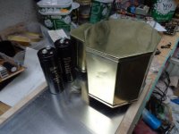
First off I'm using an existing mains tfmr and choke I have, really nice looking octaganol potted in a brass tin jobbie. Secondarys are 330v 0v 330v 6.3v 4A 6.3v 3.2A and a 2A 5v. The choke is 25H 135r DC res, so depending how I do the PSU I have 300v - 450v 80mA to play with.
Preferably the phono amp would suit MC and MM albeit with changes to the internal IP circuit and the line amp capable of at least 2v RMS out.
Here's where I get stuck: we have four basic circuits or modules, RIAA phono amp, line amp, attenuator, OP buffer (cathode follower), in what order do I place them? EG - Phono amp into line amp into attenuator into buffer? Phono and line amp switchable into attenuator into buffer?
Another question is how to configure the attenuator and what resistance to make it, my best guesstimate so far is to make it a constant Z in 100k, I have ganged 50 pole switches for this, each wafer has two 50 pole SW's on each wafer, this gives me quite a few options.
Any ideas welcome, Andy.
The problem is whilst I'm at it I might as put in a phone amp in the same chassis and could do with some advice as to how to place the various circuits.
First off I'm using an existing mains tfmr and choke I have, really nice looking octaganol potted in a brass tin jobbie. Secondarys are 330v 0v 330v 6.3v 4A 6.3v 3.2A and a 2A 5v. The choke is 25H 135r DC res, so depending how I do the PSU I have 300v - 450v 80mA to play with.
Preferably the phono amp would suit MC and MM albeit with changes to the internal IP circuit and the line amp capable of at least 2v RMS out.
Here's where I get stuck: we have four basic circuits or modules, RIAA phono amp, line amp, attenuator, OP buffer (cathode follower), in what order do I place them? EG - Phono amp into line amp into attenuator into buffer? Phono and line amp switchable into attenuator into buffer?
Another question is how to configure the attenuator and what resistance to make it, my best guesstimate so far is to make it a constant Z in 100k, I have ganged 50 pole switches for this, each wafer has two 50 pole SW's on each wafer, this gives me quite a few options.
Any ideas welcome, Andy.
Suggested order :
RIAA ( with it's own buffer ) , input selection, attenuator ( volume control),
line amp + tone controls, output buffer.
Input selection should, in a perfect amp, have trimpots to adjust levels
Output to tape / computer must come before attenuator, and should be buffered.
Mains transformer located as far as possible from riaa and inputs.
After building two big monoblocks I need a preamp to drive them, the line stage is pretty straight forward, lots of designs out there and not too hard to design one myself. <snip>
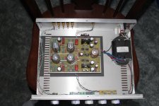
I built many of these and similar preamps, as kind of a subcontractor. This one doesn't have phono pre but a lot of them did. I would mount the line amp farther forward and a bit to the right to make room for the phono pre board, placed in the corner near the phono input jacks and as far away from the power supply as possible. There was a cathode follower buffer on the phono pre board.
We used 100K attenuators, or Alps pots, after the input selector. This one uses 6SL7's and has tone controls in a feedback loop. I built it for myself, I have an external MM/MC phono pre. I still remember a similar one I built for a gentleman that had the same line amp circuit , but used 12AX7's, and had a phono pre, with all premium coupling caps (Audiocap Theta I think) and NOS tubes. I listened to that one all night before I shipped it, it sounded lovely.
Attachments
If I can offer a couple pieces of advice…
№ 1 — Having a master volume control is the obvious and useful idea. However, I've also found that it is really helpful on a multi-input (switched source) preamp to have individual per-source “pads”. They don't even have to be on the front panel.
I've found this particularly helpful when matching up a particular volume setting on the master volume knob to the relative outputs of say 4 or more input devices. Its surprising how useful the individual pads are.
№ 2 — whatever you do to implement the moving-coil or moving magnet phono pre-preamp section, make sure it is physically isolated from the rest of the preamp. Hum and interference are all to easy for such a sensitive amplifier to pick up and inject to the rest of the network.
№ 3 — I used to like a rotary selector switch for sources (pretty “føøl-proof”), but of late I've come to like IN/OUT per-source selectors instead. There are a few {mostly-rare} occasions when having 2 sources feeding at the same time is helpful.
Just saying,
GoatGuy ✓
PS: on my 6-input most recent preamp project, since I drafted my own phono RIAA compensated network, I found it easy to include a high-gain DIN connector balanced input microphone input ... bypassing the RIAA compensation part. Fun stuff...
Nice build and layout Troy.
95k and 1.5v Koifarm, 100k pot and 1M grid leak on V1/IP at present but thought about making the pot capable of being switched out.
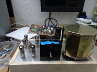
I did have a problem with 50hz hum when testing, about 60mV P-P on the OP but managed to get rid of this by building a steel can to house the RIAA amp with a very short RCA in and BNC on the OP, actually most of the hum was down to the scope lead used. On the actual amp I'll be using an IEC filter, siteing the sensitive phono amp as far away as poss from the PSU as you say and the PSU will be screened as well as the tfmr and choke being potted and in cans, see pic.
Thanks for the ideas and help lads, Andy.
95k and 1.5v Koifarm, 100k pot and 1M grid leak on V1/IP at present but thought about making the pot capable of being switched out.
I did have a problem with 50hz hum when testing, about 60mV P-P on the OP but managed to get rid of this by building a steel can to house the RIAA amp with a very short RCA in and BNC on the OP, actually most of the hum was down to the scope lead used. On the actual amp I'll be using an IEC filter, siteing the sensitive phono amp as far away as poss from the PSU as you say and the PSU will be screened as well as the tfmr and choke being potted and in cans, see pic.
Thanks for the ideas and help lads, Andy.
Attachments
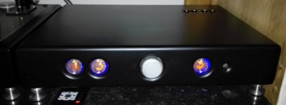
with the specs of your monoblocks i would use a passive preamp for normal sources and just a phono preamp. So input selector with relays or switch then just volume controll.
All other electronics will add distorsion, noise, humm and sound colouration.
Like on the picture i use for myself.
Remote input select and volume control(passive) and mini-me phono preamp with retro nixie volume indicator and source display.
All other electronics will add distorsion, noise, humm and sound colouration.
Like on the picture i use for myself.
Remote input select and volume control(passive) and mini-me phono preamp with retro nixie volume indicator and source display.
Attachments
Last edited:
- Status
- This old topic is closed. If you want to reopen this topic, contact a moderator using the "Report Post" button.
- Home
- Amplifiers
- Tubes / Valves
- Valve preamp.