Hi. I am building a stereo tube amp with two ELC86s. The circuit worked fine, but then I just did some "polishing" like placing the components better on the socket and I've also twisted the wires to avoid Hum.
But suddenly when I power on the amp, for a few seconds it does nothing, but then it starts oscillating like crazy! One thing I've noticed is that when I turn off the standby mode (disconnecting 300V power supply), the oscillation frequency starts to slowly drop until it disappears.
Do you know any common reasons this can happen? I've checked the circuit, but it seems completely fine. Maybe I can rebuild it, but I don't think it will help. Do you think that it can be because of the twisted wires, because I'v twisted literally every pair of wires just to be sure or can it be because of the power supply? I think not, because before it worked perfectly and now it just freaks out.
Thanks for all of your replies.
There is the schematic:

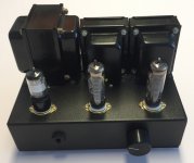
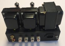
And there are some photos of that amp:
Shared album - Just Bucket - Google Photos
Like I said, it worked perfectly before, so I'm gonna do some mesauring first, the tricky part is, that I don't have an oscilloscope, only a multimeter.
And there are some photos of that amp:
Shared album - Just Bucket - Google Photos
Like I said, it worked perfectly before, so I'm gonna do some mesauring first, the tricky part is, that I don't have an oscilloscope, only a multimeter.
Did you keep the output transformer wires in the same order when you 'improved' it?
If you accidentally swapped them you may have positive feedback, not negative. Unsolder the 33k resistors and try it. If it is stable swap either the primary or secondary wires round, not both... and put the 33k back.
Not sure twisting all the wires is a very good idea either. You only need to twist the heater wires and keep them close to the chassis. You can accidentally 'couple' signals that are best kept apart by being too tidy...
You have a loose yellow cap on picture 3 ???
That loose cap is the signal input. I let it disconnected in case it would be because of that for some reason. The power transformer wires are the same, except they are twisted, but the positioning is approximately the same. I can try untwisting the plate voltage wires going to switch, because I know, that even 10cm of unshielded DC can cause oscillations not only in tube amps, but also in transistor amps.
Also the output transformers should be good, considering it was playing nicely with a little bit of hum, but one thing i did, which is true, I swapped the left and right output transformers, because the output transformer I am using now is on the correct side with the tube. I can try swapping it back and see if it will work.
Also the output transformers should be good, considering it was playing nicely with a little bit of hum, but one thing i did, which is true, I swapped the left and right output transformers, because the output transformer I am using now is on the correct side with the tube. I can try swapping it back and see if it will work.
Last edited:
Nice build. ")
Surprised those old Tesla caps still work. Old dried up capacitors might be part of the problem.
As of your newly created oscillation, clearsly some of whatn you did can cause it.
In principle, wiring lyout.
maybe that twisting plus clamping wires together as seen on puictures was not such a great idea, some cables do NOT want bto be close to others.
In principle I´d untie wraps and route signal wires, specially at the input, close to chassis and on their own path, separate from others.
It's getting worse and worse. I simplified the circuit as much as possible and the oscillation even increased. It's now extremely loud. I really don't get it. I'm gonna replace the old rectifier with a newer one just in case, but then I won't know any possible solution again. I have a 400μF capacitor in parralel just to be sure, that i have enough capacity. Those Tesla caps work, but they are both pretty low capacity.
Keep the output transformer primary winding wires as far as you can to the triode grid components. Your 10M triode grid resistor is part of the issue, the impedence on pin 1 is extremely high and will capture any nearby RF and hum. I see a 150 ohm resistor, not listed on your schematic; I don't see the 1nF capacitor at the input. Do you built a DC filament supply with the huge 6800uF 25V capacitor? This is not needed on ECL86.
I believe that your schematic taken from a tube radio is not the best available. Check out the Philips/mullard schematic. As example, there is a full schematic with explanations and voltage readings at page 37 of the "Rodenhuis Hi-Fi amplifier circuits" book (do a Google search). If you want a good example with detailed layout pictures, very similar to your schematic, check out the ECL86 amplifier published on january 1963 issue of Electronics Illustrated, page 82 ("The Mini-Fi"). This publication is available for download at American Radio History web site.
I believe that your schematic taken from a tube radio is not the best available. Check out the Philips/mullard schematic. As example, there is a full schematic with explanations and voltage readings at page 37 of the "Rodenhuis Hi-Fi amplifier circuits" book (do a Google search). If you want a good example with detailed layout pictures, very similar to your schematic, check out the ECL86 amplifier published on january 1963 issue of Electronics Illustrated, page 82 ("The Mini-Fi"). This publication is available for download at American Radio History web site.
Yes, that was one of the first thing I actually did. But when I removed it, it seemed to be a little bit worse, so I guess the problem is with the positive feedback. Just guessing.Did you try removing the 33k resistors (feedback resistors)?
Keep the output transformer primary winding wires as far as you can to the triode grid components. Your 10M triode grid resistor is part of the issue, the impedence on pin 1 is extremely high and will capture any nearby RF and hum. I see a 150 ohm resistor, not listed on your schematic; I don't see the 1nF capacitor at the input. Do you built a DC filament supply with the huge 6800uF 25V capacitor? This is not needed on ECL86.
I believe that your schematic taken from a tube radio is not the best available. Check out the Philips/mullard schematic. As example, there is a full schematic with explanations and voltage readings at page 37 of the "Rodenhuis Hi-Fi amplifier circuits" book (do a Google search). If you want a good example with detailed layout pictures, very similar to your schematic, check out the ECL86 amplifier published on january 1963 issue of Electronics Illustrated, page 82 ("The Mini-Fi"). This publication is available for download at American Radio History web site.
Wow, those schematics seems to be really good and relatively simple to build. Guess I'm gonna spend some extra money on a new parts. I am filtering the DC fillament just to be sure the hum doesn't go from there. There is a 1nf cap on pin 1, maybe it's just not clearly vidible, but it's there.
What resistor value would you choose instead of that 1M? 220k would be fine? And that 150ohm resistor, I thought, that both triode and pentode have 150ohm cathode resistor, on the pentode section, it's just missing the "R".
Thanks for your reply, gonna try one of those schematics for sure.
I have built the Mullard circuit listed on Rodenhuis book, with the following modifications:
- 4k grid stopper resistor directly mounted on pin 1. As I mentioned on my previous post, according to my experience ECL/PCL86 tube is prone to oscillations, much more than ECL85 or ECL82 or 6F3.
- I removed the tone controls, and added 1M grid leak resistor on the triode (pin 1).
- I changed the C2/R3 values to adapt the circuit to my output transformer (I selected 150pF/1k). As mentioned on the book, this circuit does require a good quality output transformer. If the quality is too low, the global feedback must be reduced (increase R3).
- silicon rectifier on the b+ power supply (fast silicon carbide diodes).
The filament supply is AC. No hum at all.
This is the finished amplifier. Magic eye tube is EAM86. The chassis is a standard electrical metal enclousure box 222 x 146 x 56 mm. Easy to source, as example: RS components 517-3260. If you choose this one, be sure to have proper drilling bits because it much thicker than regular aluminium enclousures such as Hammond 1444-1172 (a good choice for this amplifier, because it is bigger and you could increase the space between output and power transformer). I powder coated it after drilling.
Attachments
Well guys, I think I found it. I swapped the 10nF cap for some 22nF one and the oscillation changed significantly. It is much much higher now. The cap is foil one, so do you think it might me it? If I just change the capacitor to its right value, will it work again?
Mr. pcan, I really admire your work. It's just beatiful and I bet it sounds even better. I'm gonna build the amp with your recommendations, because I don't know some things yet and best way to learn it is to really apply them in the real world. Thank you, this will really move me forward.
Yes, it was really the faulty capacitor. I thought they would last longer, as I have it like 14 days or so, and they were from Tesla. Well, nevermind. So because of one cap I completely remade the entire thing, damn .
Anyway, thank you all for your answers, it helped me a lot.
I'm gonna order the new parts now and star all over again.
Mr. pcan, I really admire your work. It's just beatiful and I bet it sounds even better. I'm gonna build the amp with your recommendations, because I don't know some things yet and best way to learn it is to really apply them in the real world. Thank you, this will really move me forward.
Yes, it was really the faulty capacitor. I thought they would last longer, as I have it like 14 days or so, and they were from Tesla. Well, nevermind. So because of one cap I completely remade the entire thing, damn
. Anyway, thank you all for your answers, it helped me a lot.
I'm gonna order the new parts now and star all over again.
Lesson learned: when you’re changing stuff, make one small change at a time then retest to get a new base line. That way the faulty component or bad thing that you did will be readily visible. For example change one cap at a time then retest. Make one wire change at a time then retest, etc.
Last edited:
- Status
- This old topic is closed. If you want to reopen this topic, contact a moderator using the "Report Post" button.
- Home
- Amplifiers
- Tubes / Valves
- Oscillation in ECL86 amp