Hi,
For the Baby Huey amplifier (designed by yvesm and gingertube) I have made 3 different PCB, one very simple for two ECL86 or PCL86, a more complicated one for one ECC83 and two EL84 with a MOSFET driver stage and a similar schematic but for EL34 output tubes to have more power ( https://www.diyaudio.com/forums/tubes-valves/326920-el34-baby-huey-amplifier.html ) ... I was not only impressed by the quality of the sound of these little amplifiers but also by the huge interest of the audio community and with the help of Prasi more than 500 boards have been produced for these PCB
After this experience, when I read somewhere that the Simple Quasi Complementary MOSFET Amplifier (designed by Ranchu32) sounded a little like a tube amplifier ( https://www.diyaudio.com/forums/solid-state/255427-simple-quasi-complimentary-mosfet-amplifier.html ) I could not resist and I decided to make a PCB to test it... I was not disappointed at all")
An other experience with My MOSFET Amplifier designed for Music (designed by Mooly) witch also impressed me ( https://www.diyaudio.com/forums/solid-state/119151-mosfet-amplifier-designed-music.html ) finished to convince me that a "Best of both World" solution could be to make an Hybrid Amplifier which will use tubes in their best job to increase voltage and transistors with their capability to drive high current at low impedance therefor we could avoid the expensive and heavy output transformers
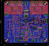
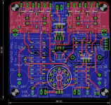
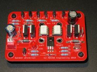
During my build of the Quasi I had the chance to have a lot of support from Hugh (AKSA) and we discussed the hybrid amplifier. From these discussions I have designed not one but two PCB : rev.5 is the original project with a current source and Rev.5 HD is Hugh suggestion to use a mu-follower stage...
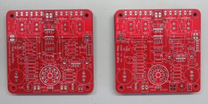
Now that I have finally received the PCB I will start to build and test them
Cheers,
Marc
For the Baby Huey amplifier (designed by yvesm and gingertube) I have made 3 different PCB, one very simple for two ECL86 or PCL86, a more complicated one for one ECC83 and two EL84 with a MOSFET driver stage and a similar schematic but for EL34 output tubes to have more power ( https://www.diyaudio.com/forums/tubes-valves/326920-el34-baby-huey-amplifier.html ) ... I was not only impressed by the quality of the sound of these little amplifiers but also by the huge interest of the audio community and with the help of Prasi more than 500 boards have been produced for these PCB
After this experience, when I read somewhere that the Simple Quasi Complementary MOSFET Amplifier (designed by Ranchu32) sounded a little like a tube amplifier ( https://www.diyaudio.com/forums/solid-state/255427-simple-quasi-complimentary-mosfet-amplifier.html ) I could not resist and I decided to make a PCB to test it... I was not disappointed at all
An other experience with My MOSFET Amplifier designed for Music (designed by Mooly) witch also impressed me ( https://www.diyaudio.com/forums/solid-state/119151-mosfet-amplifier-designed-music.html ) finished to convince me that a "Best of both World" solution could be to make an Hybrid Amplifier which will use tubes in their best job to increase voltage and transistors with their capability to drive high current at low impedance therefor we could avoid the expensive and heavy output transformers
During my build of the Quasi I had the chance to have a lot of support from Hugh (AKSA) and we discussed the hybrid amplifier. From these discussions I have designed not one but two PCB : rev.5 is the original project with a current source and Rev.5 HD is Hugh suggestion to use a mu-follower stage...
Now that I have finally received the PCB I will start to build and test them
Cheers,
Marc
Attachments
I am following this project with great interest. Hopefully it works very well and satisfy your desire for the “best of both worlds”. Also hope Prasi would be involved in doing a GB. (I’m still, happily, working through my BH boards).
Two comments for your consideration, Marc.
1. Please consider designing your Quasi around current production output Mosfets. I had heard the supply status of those you have in the schematic is doubtful.
2. I see on the PCB that you make allowance for using the 6N1p. That is good, because I have seen many comments by gurus on this forum that ECC82 is not a very linear voltage amplifier. 6N6p would be even better, as would 6CG7 be.
Be aware that lateral power mosfets have a large and unlinear input capacitance and to reduce high frequency distortion, they should therefore be driven by a low impedance source, I don't know the output impedance of the tube driver, but even the gate resistors are too large....
Good alternatives to the now unavailable Hitachi Lateral Power Mosfets parts are Exicon, available at Profusion.
The output mosfet relay are a good choice, but they should be protected, t.ex. by a TVS.
The gate protection zeners should also have a series diode, otherwise they conduct when you don't want them to.
Last edited:
Hi,
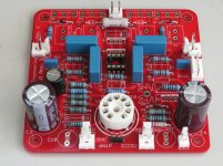
I have started to build this amplifier but I sill need some components and I just send an order to Mouser
While I have done this work, I made some changes for several resistors values that I show in this new schema... For the output transistors the lateral MOSFET from Renesas that I am also using on the Amplifier made for music from Mooly are doing well and as soekris say you can get equivalent from Exicon, they are only a little bit more expensive
The jumper selection for heater of the 6N1P can also be used to test other tubes like the 6FQ7 or 6CG7 ( https://s3.amazonaws.com/tubedepot-com-production/spree/attached_files/6cg7eh.pdf?1400185580 ). The ECC99 could be also interesting ( https://www.jj-electronic.com/images/stories/product/preamplifying_tubes/pdf/ecc99.pdf ) with the jumper on the ECC82 position.
For the SSR protection I forget the TVS protection, it is stupid because I have done it on an other DC protection
Rgds,
Marc
Attachments
Have you listened to this with and without the muting transistors on the output?
After done such a listen many years ago I have banned the use of transistors for muting. I only use relays if I bother with muting at all. I think the bad sound is due to the nonlinear capacitance of transistors. But perhaps todays transistors are much better?
After done such a listen many years ago I have banned the use of transistors for muting. I only use relays if I bother with muting at all. I think the bad sound is due to the nonlinear capacitance of transistors. But perhaps todays transistors are much better?
Hello John,
I am using the old version 7 of Eagle, I found it quite easy to use but I still learn few trick from Prasi who is an Eagle Expert There is a lot of support like tutorial and library on the web. There is also a free version for boards less than 10 cm x 8 cm with two sides...
There are other CAD software like KiCad KiCad EDA that I don't like, too complicated for me, DipTrace DipTrace - Schematic and PCB Design Software and EasyEDA EasyEDA - Online PCB design & circuit simulator it is free but you have to buy PCB from them...
I have tested the last Eagle version 9.2 that Prasi is using but even if it is more performant, I found it more difficult to use
For PCB manufacturing, I am using PCBWay since 2 years : China PCB Prototype & Fabrication Manufacturer - PCB Prototype the Easy Way They have a good service and a price of 5$ for 10 PCB of less than 10 cm x 10 cm However with the last shipment there was a problem with the carrier E-Packet and the boards were blocked in Beijing during 4 weeks ! Finally PCBWay sent them by DHL at their own cost 
Rgds,
Marc
I am using the old version 7 of Eagle, I found it quite easy to use but I still learn few trick from Prasi who is an Eagle Expert
There is a lot of support like tutorial and library on the web. There is also a free version for boards less than 10 cm x 8 cm with two sides...There are other CAD software like KiCad KiCad EDA that I don't like, too complicated for me, DipTrace DipTrace - Schematic and PCB Design Software and EasyEDA EasyEDA - Online PCB design & circuit simulator it is free but you have to buy PCB from them...
I have tested the last Eagle version 9.2 that Prasi is using but even if it is more performant, I found it more difficult to use
For PCB manufacturing, I am using PCBWay since 2 years : China PCB Prototype & Fabrication Manufacturer - PCB Prototype the Easy Way They have a good service and a price of 5$ for 10 PCB of less than 10 cm x 10 cm
However with the last shipment there was a problem with the carrier E-Packet and the boards were blocked in Beijing during 4 weeks ! Finally PCBWay sent them by DHL at their own cost Rgds,
Marc
Hello Sodacose, Hello carlsor,
Following your post, I had a look to the Moskido design, it is interesting but I wanted to have a compact solution with all on 1 board and I also don't like to have a SRPP with a tube having its cathode at 150 V which need to set the heater voltage at 75 V, I prefer to use MOSFET since I have found that they sound very well in source follower application...
I have not decided for the idle output current, I will see during test but 75 to 100 mA could be a good value ?
Rgds,
Marc
Hello stocktrader200,
The 6922, ECC88 and 6DJ8 can be tested with the heater jumper om 6N1P position...
Hi SemperFi,
The MOSFET on the output are not for muting but they are used as a SSR to protect speaker against DC voltage during power up or in case of problem !
Rgds,
Marc
PS: I have just received missing components from Mouser, I will continue to build the amplifier
Hi,
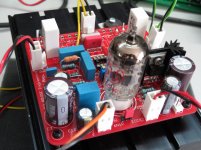
The Hybrid project is not going very well as I had several problems
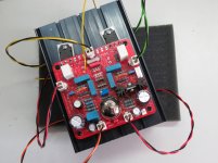
First I have been catch again by a transistor pinout difference between vertical MOSFET like the IRFP940 and the lateral MOSFET used in this amplifier. I found it too late and I had to remove the output transistors and to cross the legs with an isolation before to continue the test...
Unfortunately, when I powered the amplifier after the modification I made a stupide mistake (in French we even say a "connerie" but I don't know the English version ?) I connected the positive power supply on the negative input and the opposite for the negative power supply
I have changed the MOSFET again but the amplifier still didn't work
I can listen only a very low level of music when the input is at the maximum
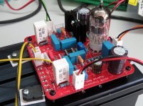
Since I found on the scope that the music signal was present on the plate of the tube but not on the source of the MOSFET in the SRPP, I decided to change the DN2540 without more success
Now the board is no more usable, too much desoldering I will build a second board based on rev. 5 HD with Hugh Dean suggestion of a Mu-follower stage designed by Alan Kimmel instead of the SRPP stage with a MOSFET found in the Merlin Book...
May be the very high temperature don't motivate me to make test, even if my lab has air conditioning
Bye,
Marc
The Hybrid project is not going very well as I had several problems
First I have been catch again by a transistor pinout difference between vertical MOSFET like the IRFP940 and the lateral MOSFET used in this amplifier. I found it too late and I had to remove the output transistors and to cross the legs with an isolation before to continue the test...
Unfortunately, when I powered the amplifier after the modification I made a stupide mistake (in French we even say a "connerie" but I don't know the English version ?) I connected the positive power supply on the negative input and the opposite for the negative power supply
I have changed the MOSFET again but the amplifier still didn't work
I can listen only a very low level of music when the input is at the maximum
Since I found on the scope that the music signal was present on the plate of the tube but not on the source of the MOSFET in the SRPP, I decided to change the DN2540 without more success
Now the board is no more usable, too much desoldering
I will build a second board based on rev. 5 HD with Hugh Dean suggestion of a Mu-follower stage designed by Alan Kimmel instead of the SRPP stage with a MOSFET found in the Merlin Book...May be the very high temperature don't motivate me to make test, even if my lab has air conditioning
Bye,
Marc
Attachments
Hi Kay Pirinha,
I have no offset problem, it can be adjusted with R17 !
To give more information about this project, it all started with a schematic that I found on the Web in the early 2000 : 6FQ7/6SN7 + MOS. FET Hybrid power amplifier I wanted to build this amplifier since a long time, but I didn't like to use a second tube in the SRPP because of the elevated heater supply and when I found in Merlin Blencowe book that MOSFET could replace vacuum tube in cathode follower applications (see attachement), I decided to give it a try, that is Rev. 5
During some exchanges with Hugh Dean, he suggested tu use a Mu-follower instead of a SRPP and recommended Alan Kimmel approach http://www.fetaudio.com/wp-content/uploads/2003/09/Mu-Stage.pdf see fig. 5 page 3... This is Rev. 5 HD
As Hugh said Hybrid amplifier are not easy to make, but when correctly designed they are sounding very well, therefor I have to work on it to find the solution
Rgds,
Marc
- Home
- Amplifiers
- Tubes / Valves
- Simple Hybrid tube amplifier with MOSFET output