I didn't post a thread about it. Just posted the schematic on a thread asking for RIAA designs...
However, I'm building a tube version today complete with "Janus" regulation.
It'll be a tight build... 9x5x2 inch chassis, 10 tubes, DC-DC boost converter... The last such build saw a board get hot enough the solder melted and a capacitor FELL OUT.
However, I'm building a tube version today complete with "Janus" regulation.
It'll be a tight build... 9x5x2 inch chassis, 10 tubes, DC-DC boost converter... The last such build saw a board get hot enough the solder melted and a capacitor FELL OUT.
Thanks Koda - found it!
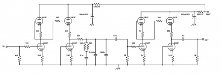
RIAA network on cathode follower
I was interested in valve RIAA circuits because there are two spare holes in the chassis I am rebuilding so I wanted to do a two-triode phono stage. Clearly yours is not suitable although clearly superior!
I also saw your dabbling in the dark side over in the sand section.....
Glad you found it. I should bookmark it myself ")
I found this over at head-fi: Tube Phono and PS Questions | Headphone Reviews and Discussion - Head-Fi.org
I can't tell you how good it will be, but it looks like the gain is on the low side.
There is also the original RCA circuit from the 50's, but it sucks. However if you're not opposed to a little "dark side" of your own, Eli has a very cool play on the RCA that can be found here: Want help - RCA Tube Manual RIAA Phono Stage
I'll be using LM4562NA: http://www.ti.com/lit/ds/symlink/lm4562.pdf
Yep, tho' if you take a look at the IM4562.PDF file, it also has a “passively filtered RIAA” implementation. Curiously, it specifies a bunch of different capacitor values in parallel; in one sense I suppose it is to get the “values between”, (while capitalizing on the inverse-additive nature of imprecision), in another sense, especially with the 1,000 pF cab in parallel with the rest, I'm pretty sure that's to address HF roll off of larger value capacitors. Or not. Who knows.
Just saying,
GoatGuy ✓
The 1000 pf is to get 0.034uf for the filter since 0.033 is the wrong value. Yes, in reality, it's pretty close. If you're building a one off for yourself, why not try and get the filters bang on though, right? Same as the 3k3 || 100k. Makes 3180 or so so that part of the filter will be more accurate.
I used to split the equalization into two different sections. It's more accurate but requires another stage.
I used to split the equalization into two different sections. It's more accurate but requires another stage.
Last edited:
This was the first phono amp I built. I liked it but there is less noise with the active loaded follower designs.
Bob's Vacuum Tube Phono Preamp
Bob's Vacuum Tube Phono Preamp
Then there is Broskie's approach:
The Tube CAD Journal: Split Equalization Passive Preamps
Phono Preamps at Last
The Tube CAD Journal: Split Equalization Passive Preamps
Phono Preamps at Last
No difference really... The grid is still grounded in the first one albeit through a 100k resistor. This resister along with another and a cap can be used for Broskies' Aikido PS noise nulling. I removed it since I don't use Aikidoing.
I find this circuit will work from about 200V to 350V without changes but the higher end of the voltage scale is preferred if you have it. The above example using 280V is based on an eBay 12V to 280V DC boost converter.
I've also changed the 1M on the output to 100k.
I find this circuit will work from about 200V to 350V without changes but the higher end of the voltage scale is preferred if you have it. The above example using 280V is based on an eBay 12V to 280V DC boost converter.
I've also changed the 1M on the output to 100k.
Last edited:
- Status
- This old topic is closed. If you want to reopen this topic, contact a moderator using the "Report Post" button.
- Home
- Amplifiers
- Tubes / Valves
- Replacing valves.