…and I love it.
A bit of background: I started this amp about a decade ago. All I knew was that I wanted an Ultralinear push-pull EL-84 amp. The design began as a self-splitting output stage driven by an op-amp. It then changed to being driven by another EL-84. It changed again to a very traditional design of a grounded cathode, concertia phase splitter, and traditional grounded cathode output. I ended up going that direction with this amp I built for a friend:
Just what the world needs - another EL84 amp
I’m the kind of person that wants to try something new and didn’t want to repeat myself, so the amp morphed into a DAC directly coupled to a 6N1P differential amp, followed by a differential output pair. Progress stalled as life got hectic. About a year ago I decided that I was going to get this amp done. I had recently read Broskie’s blog on the “Bastode Aikido FET amplifier” here:
RMAF 2017 near the bottom of the page.
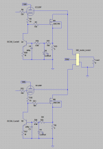
I fired up LTSpice and changed the input tube to a 6N1P (my favorite little small signal triode). I adjusted a few values to work better with the 6N1P, and then decided that the follower in the circuit was going to have to do double duty to earn its keep. I changed it to a concertina type phase splitter, and used a voltage divider on the bottom of the concertina to act as both a bias and feedback for the 6N1P. I also replaced the tube in the concertina splitter with a MOSFET (a FQPF2N80, I don’t have a LTSpice model to show it on the schematic) because in a follower role, it does everything better. Much greater transconductance, less internal resistance, greater voltage swing, no heater power or heater lift needed, electrically insulated package, tiny input capacitance, and smaller footprint.
Next, I had to decide how to bias the output tubes. I had just built a guitar amp for a friend that used a garter bias, so I didn’t want to do that again. I didn’t want to build a separate power supply for negative bias and wanted to avoid manually adjusting the bias, but I couldn’t decide whether to use bypassed constant current sources or LED bias like the RLD. I compromised by doing both. I put in a quad-pole-double-throw switch that goes from the cathodes to either bypassed constant current sources or a 5x6 yellow LED array.
Component choices:
I’m using 6N1Ps for the input and 6P14P-EV tubes for the output. I wired the sockets so they could accept 6P15P tubes if I want to try those in the future. I bought two Edcor 25w Ultralinear X-class transformers when I started this project. For the main PSU I found a Hammond 110-100v 100VA transformer on ebay that I’m using backward to get about 310v DC. I designed a PCB to hold all of the components except the power supply and output tubes. Normally I use mostly industrial poly caps, but I splurged and (somehow) fit in Dayton and Janzen film caps and a few silver mica bypass caps.
Power supplies:
I’m a big fan of regulated supplies, but I wasn’t sure what voltage the output tubes would land at with changes in the line voltage, so I made a PCB to house a ripple smoother and the LED array for the cathode. The ripple filter is a voltage divider that takes the ~310v DC and uses a MOSFET follower (some high voltage TO-247 I had laying around) to provide a fairly clean 300v for the output tubes. Another MOSFET regulator fed by a bypassed Zener string gives a very clean 240 volts for the signal circuitry. I’m using a 12v switchmode PSU for the heaters. The 6N1P uses a 10 ohm 10 watt dropping resistor to run at the right voltage. I’m beginning to believe that this is the best (but not most efficient) approach for using switchmode PSUs on heaters. The increased resistance while cold keeps the current draw of the heaters reasonable and keeps the PSU from auto turning off.
A bit of background: I started this amp about a decade ago. All I knew was that I wanted an Ultralinear push-pull EL-84 amp. The design began as a self-splitting output stage driven by an op-amp. It then changed to being driven by another EL-84. It changed again to a very traditional design of a grounded cathode, concertia phase splitter, and traditional grounded cathode output. I ended up going that direction with this amp I built for a friend:
Just what the world needs - another EL84 amp
I’m the kind of person that wants to try something new and didn’t want to repeat myself, so the amp morphed into a DAC directly coupled to a 6N1P differential amp, followed by a differential output pair. Progress stalled as life got hectic. About a year ago I decided that I was going to get this amp done. I had recently read Broskie’s blog on the “Bastode Aikido FET amplifier” here:
RMAF 2017 near the bottom of the page.
I fired up LTSpice and changed the input tube to a 6N1P (my favorite little small signal triode). I adjusted a few values to work better with the 6N1P, and then decided that the follower in the circuit was going to have to do double duty to earn its keep. I changed it to a concertina type phase splitter, and used a voltage divider on the bottom of the concertina to act as both a bias and feedback for the 6N1P. I also replaced the tube in the concertina splitter with a MOSFET (a FQPF2N80, I don’t have a LTSpice model to show it on the schematic) because in a follower role, it does everything better. Much greater transconductance, less internal resistance, greater voltage swing, no heater power or heater lift needed, electrically insulated package, tiny input capacitance, and smaller footprint.
Next, I had to decide how to bias the output tubes. I had just built a guitar amp for a friend that used a garter bias, so I didn’t want to do that again. I didn’t want to build a separate power supply for negative bias and wanted to avoid manually adjusting the bias, but I couldn’t decide whether to use bypassed constant current sources or LED bias like the RLD. I compromised by doing both. I put in a quad-pole-double-throw switch that goes from the cathodes to either bypassed constant current sources or a 5x6 yellow LED array.
Component choices:
I’m using 6N1Ps for the input and 6P14P-EV tubes for the output. I wired the sockets so they could accept 6P15P tubes if I want to try those in the future. I bought two Edcor 25w Ultralinear X-class transformers when I started this project. For the main PSU I found a Hammond 110-100v 100VA transformer on ebay that I’m using backward to get about 310v DC. I designed a PCB to hold all of the components except the power supply and output tubes. Normally I use mostly industrial poly caps, but I splurged and (somehow) fit in Dayton and Janzen film caps and a few silver mica bypass caps.
Power supplies:
I’m a big fan of regulated supplies, but I wasn’t sure what voltage the output tubes would land at with changes in the line voltage, so I made a PCB to house a ripple smoother and the LED array for the cathode. The ripple filter is a voltage divider that takes the ~310v DC and uses a MOSFET follower (some high voltage TO-247 I had laying around) to provide a fairly clean 300v for the output tubes. Another MOSFET regulator fed by a bypassed Zener string gives a very clean 240 volts for the signal circuitry. I’m using a 12v switchmode PSU for the heaters. The 6N1P uses a 10 ohm 10 watt dropping resistor to run at the right voltage. I’m beginning to believe that this is the best (but not most efficient) approach for using switchmode PSUs on heaters. The increased resistance while cold keeps the current draw of the heaters reasonable and keeps the PSU from auto turning off.
Attachments
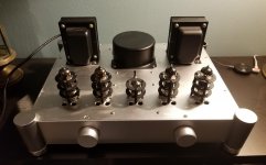
Case:
I bought a fairly large somewhat finished aluminum amp case off of ebay. I drilled a bunch of holes (I like to use Front Panel Express software to do the design, then print it out and centerpunch/drill off of that) for tubes, ventilation, tube guards, and everything else. I went with a black and silver theme, I think it turned out OK. The right knob is for volume and the left knob is a rotary switch from a lamp that is used for power on/off.
Inside:
Inside you can see the general layout. This picture was taken at the 95% completion point while doing some power up tests. You can see the yellow glow from the LED array that biases the cathode(s). It was still missing a few things like chassis grounding and some miscellaneous wiring. Not shown is the bottom panel, which might be too extreme for some of our more sensitive readers. It contains a…fan. Don’t worry, it’s a 92mm Noctua fan run at 9v off of a LM317. It produces a broad spectrum of noise instead of a single tone, and at 9v it’s inaudible from more than a foot.
Those with keen eyesight among you may have noticed four small black cylinders at one edge of the main PCB. Those constitute a LDR volume control. That’s a subject for a different post, but it works brilliantly. It’s especially well suited for devices with a high input impedance like tubes or jfets.
Listening:
I loaded up some old 6P14P tubes and a new 6N1P and powered on. When cold, the 12v psu cycles 2-3 times before the heater resistance is high enough that it doesn’t trip the 6 amp limit. The first test run was a disaster – after a few seconds it sounded like I was being strafed by a Spitfire. A high pitch that descended rapidly followed by a rapid oscillation. I traced it to the scummy old tubes that I was testing with and threw them away. I tried some more used tubes and had it working, but one channel was noticeably louder than the other. After ensuring that no fire would come belching out, I borrowed a matched quad of output tubes, and voila, sweet music! I won’t try to sell anyone with audiophile adjectives, but the sound was a huge improvement over the TPA3116 that had been there before. The CCS mode is extremely bass heavy, which can be good to offset bookshelf speakers with limited bass, but on full range speakers it’s distracting. The LED biasing on the other hand is fantastic. Everything is clear, neutral, and just right.
Attachments

Thanks for the detailed write-up, interesting reading 🙂. Good use of mosfet concertina, I agree with all your arguments for it. I haven't tried the Bastode yet, but seems to sim nicely with a good distortion profile. You might want to check the grid to cathode voltage for the 6n1p, the sim says it is very close to zero. Reducing the value of R11/R22 helps, but I guess it depends on the particular tube you are using.
Interesting observations of bass response of CCS vs LED array. Running 6BQ5's ultralinear with no NFB results in quite high output impedance so there will be a response peak at the speaker fs assuming closed box, and peaks elsewhere depending on the crossover. The simulation says about 10 ohms at best (fixed bias), I guess the CCS makes this worse. LED array acts much like fixed bias.
How is bias current matching with the LED arrays? SY had variable screen voltage in the RLD to adjust current, you obviously can't do that with ultralinear connection.
Hi!
Very interesting circuit! Why did you remove the power supply noise injection (series RC from supply to 6N1P grid) that Broskie had foreseen? He called it some "aikido mojo".
Cheers,
M.
Very interesting circuit! Why did you remove the power supply noise injection (series RC from supply to 6N1P grid) that Broskie had foreseen? He called it some "aikido mojo".
Cheers,
M.
I removed the noise injection because I like to overbuild power supplies. Using a regulated supply, the supply impedance is less than an ohm and ripple is trivially low. No point in compensating for something that doesn't exist in any realistic amount. To the point, I have to put my ear 1" from the tweeter to start to hear any background hiss. The price is that I burn about 50 volts at less than 20ma (about a watt) for the front end.
I made a hybrid of: 12AX7 > Ksc3503 concertina > 6922 + Mje13007 > 2k transformer ( no feedback ) = 30 fantastic watts at 160v B+.
May be the best sounding amp I have made yet.
May be the best sounding amp I have made yet.
Last edited:
Any voltage on the grid of the 6N1P has practically no effect on the anode voltage, the current is in the triode determined by the fet and so is the voltage drop on R6.Hi!
Very interesting circuit! Why did you remove the power supply noise injection (series RC from supply to 6N1P grid) that Broskie had foreseen? He called it some "aikido mojo".
Cheers,
M.
Only the cathode voltage = drain voltage fet is fixed by the grid voltage.
But yes, there is a very small change.As the Vag changes the -Vg changes also since the current is fixed.
Mona
I made a hybrid of: 12AX7 > Ksc3503 concertina > 6922 + Mje13007 > 2k transformer ( no feedback ) = 30 fantastic watts at 160v B+. May be the best sounding amp I have made yet.
Its a funny thing, your heartfelt opinion, and my secret projects … hybrid … using either MOSFETs or (like you) BJTs that are stout, common-range-as-valves … and an output impedance matching transformer. When we search for linearity, those power BJTs are kind of hard to beat, especially for the price and operational longevity.
Was your MJE13007 driven in emitter-follower mode, or as a more conventional like-an-output-tube fashion? I've been toying with BJTs (and MOSFETs) in push-pull emitter-follower (source-follower) with varying success.
Remarkable sound.
And power too...
Just asking,
GoatGuy
Hi Goatguy, I used the MJE13007 as a current booster following the tube so that the tube characteristics dominate. the schematic is here. 3 x 3 Tube amp 30 watts
tikiroo - I'm not sure the J177 Spice model is terribly accurate. JFETs can range greatly from their statistical mean, which is what Spice models. I'm getting about a volt between the grid and cathode, so I'm about right. I think that there's a bit of self-bias in the circuit where reduced voltage between the grid and cathode decreases the voltage at the anode, which then reduces the voltage at the divider, thereby increasing the voltage between the grid and cathode. It's a limited amount of negative feedback at both AC and DC. JFETs or tubes that are significantly out of spec from the spice model could exceed the limits of adjustment, but so far so good.
GoatGuy - my next amp is going to be a crazy mashup of JFETs, transformers, tubes, and high voltage MOSFETs, all put in non-traditional configurations. But that will be a separate post when I'm further along.
GoatGuy - my next amp is going to be a crazy mashup of JFETs, transformers, tubes, and high voltage MOSFETs, all put in non-traditional configurations. But that will be a separate post when I'm further along.
Hi Goatguy, I used the MJE13007 as a current booster following the tube so that the tube characteristics dominate. the schematic is here. 3 (repl \ with slash) x 3 Tube amp 30 watts
What a remarkable circuit.
After as many decades as I've been designing topologies from the mundane to the opaquely clever, I don't think I'd've come up with that little gem-in-the-finals.
Really nice idea.
I bet there is a fair bit of sensitivity choosing the resistor above the 1N4700 (or whatever it is) diode to get linear-over-signal-range transistor response. Not a place-holder that!
How say you again, regarding its dynamics? I like it.
Just saying,
GoatGuy
Thanks Goatguy. I have not seen that implementation before or since I posted the circuit.
The 2.2k ensures that the MJE13007 remains fast. Frequency response extends well past 50khz flat. The 6922 cannot drive the transistor into saturation thereby keeping it in the linear range. This amp is essentially a power 6922 with ( up to ) 1A of current and 50w plate dissapation.
The 2.2k ensures that the MJE13007 remains fast. Frequency response extends well past 50khz flat. The 6922 cannot drive the transistor into saturation thereby keeping it in the linear range. This amp is essentially a power 6922 with ( up to ) 1A of current and 50w plate dissapation.
Attached is the output stage of my latest amp. It is similar topology to Stocktrader's (it's another Broskie idea) but biasing is more complex with the mosfet instead of BJT. The npn acts as a bias servo for the mosfet as well as a CCS for the pentode. The clipper LED allows servo operation into class AB. The pentode needs ~ -11V on its grid (allows trimming of current), or a larger value cathode resistor to get the voltages right for the mosfet. Feedback to the screen makes the pentode behave like a triode, without the plate current passing through the output transformer.
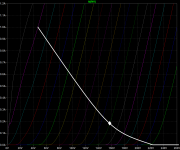
The valve/mosfet arrangement acts like a triode with gm of 150 mA/V, rp of 50 ohms and mu of 7.5. See attached spice generated curves and approximate loadline with 400:8 output transformer (a 30V mains toroid). It's good for more than 50 watts into 8 ohms. I can't fault the sound or measurements, only hassle is the heatsinks.
Sorry for the threadjacking Fenris, but you did mention "a crazy mashup of JFETs, transformers, tubes, and high voltage MOSFETs" 😀
Attachments
On simulator at 4ma the j177 has drain impedance of about 30k . This provokes a NFB of 6db .Any voltage on the grid of the 6N1P has practically no effect on the anode voltage, the current is in the triode determined by the fet and so is the voltage drop on R6.
Only the cathode voltage = drain voltage fet is fixed by the grid voltage.
But yes, there is a very small change.As the Vag changes the -Vg changes also since the current is fixed.
Mona
You mean the supertriode?Thanks Goatguy. I have not seen that implementation before or since I posted the circuit.
SuperTriode
Sorry for the threadjacking Fenris, but you did mention "a crazy mashup of JFETs, transformers, tubes, and high voltage MOSFETs" 😀
Actually tikiroo, that's almost exactly the same topology that I'm working on, except using a 6J11P (6688, EF180) and independent constant current sources for the tube and mosfet.
Tikiroo, Your circuit will behave differently as the plate is connected to B+ and the output is driven from the mosfet and the screen (upper) grid.
I hadn't seen this done with a BJT, Broskie's supertriode setup has the mosfet transistor characteristics equal to if not dominate the triode characteristics.
A mosfet is a crappy substitute in my circuit
I hadn't seen this done with a BJT, Broskie's supertriode setup has the mosfet transistor characteristics equal to if not dominate the triode characteristics.
A mosfet is a crappy substitute in my circuit
Last edited:
The output isn't driven by the screen grid (it's only a tiny fraction of the total current), the output drives the voltage on the screen grid which acts as a feedback mechanism to the pentode.
Tikiroo or Fenris, what is the effect on plate current using the screen grid?
for instance, it is not possible to drive the transistor into saturation because the tube cannot pass 10ma with less then 25 volts plate to cathode. I am assuming your circuit can drive the transistor right to the rails
for instance, it is not possible to drive the transistor into saturation because the tube cannot pass 10ma with less then 25 volts plate to cathode. I am assuming your circuit can drive the transistor right to the rails
Last edited:
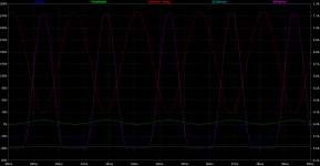
Hi Stocktrader. The mosfet can't be driven to the rails, the valve/mosfet combo clips with onset of grid current, just like a normal output valve (without cathode or source follower driving it). The plate current remains constant by design. With positive going grid voltage there is a positive going cathode voltage which increases mosfet current and results in a negative going drain/screen voltage. The AC amplitude at the cathode is much less than the AC amplitude at the grid due to the feedback through the screen. See attachment which shows conditions at clipping.
Actually there is little difference in performance with a real triode or the pentode connected as a triode (plate+screen connected to mosfet drain) or with only the screen connected to mosfet drain. With a triode, the voltage feedback is through the plate rather than the screen. The advantage of using the screen for feedback is that most of the constant current through the valve is coming directly from B+ rather than going through the output transformer where it is not doing anything useful.
Actually there is little difference in performance with a real triode or the pentode connected as a triode (plate+screen connected to mosfet drain) or with only the screen connected to mosfet drain. With a triode, the voltage feedback is through the plate rather than the screen. The advantage of using the screen for feedback is that most of the constant current through the valve is coming directly from B+ rather than going through the output transformer where it is not doing anything useful.
Attachments
- Status
- Not open for further replies.
- Home
- Amplifiers
- Tubes / Valves
- So, I built a Broskie Bastode…