I'm using the 900V version at 6 mA.
The datasheet for this part is https://www.mouser.com/datasheet/2/240/DS98729A(IXCP-CY10M90S)-1547388.pdf … and it indicates a dynamical impedance of 30 kΩ, minimum. Real parts will vary.
GoatGuy ✓
--- No. ---
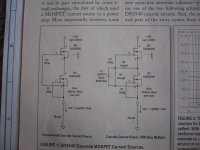
The 'R' in the above formula is the R needed in series with the cathode of the current-regulator chip to 'set-point' its current value.
The datasheet (pdf, which I included a link to) itself states the dynamic impedance of the chip as a current source. a minimum of 160 kΩ…
You're welcome.
In advance.
Just Saying,
GoatGuy ✓
OK, got it. Thanks.
The datasheet for this part is https://www.mouser.com/datasheet/2/240/DS98729A(IXCP-CY10M90S)-1547388.pdf … and it indicates a dynamical impedance of 30 kΩ, minimum. Real parts will vary.
GoatGuy ✓
And the 450 Volt version gives Rdyn minimum of 10K, so that would indicate that the 900 Volt version is even higher than the 160K that you mentioned.
--- No. ---
The 'R' in the above formula is the R needed in series with the cathode of the current-regulator chip to 'set-point' its current value.
The datasheet (pdf, which I included a link to) itself states the dynamic impedance of the chip as a current source. a minimum of 160 kΩ…
You're welcome.
In advance.
Just Saying,
GoatGuy ✓
This is where that confusion arises. The IXCP 10M45S data sheet for the same item that I have shows a completely different minimum dynamic resistance (10K). You got the Mouser version. This is a mystery.
Attachments
So… again being a curious old goat, I took the datasheet of the 10m90S and “gave it a go” from a curve-fitting perspective. To a r-squared accuracy over 0.9998 (i.e. excellent), we have this formula:
I'm rather pleased with myself.
More coffee.
Ho, ho, ho!
Just Saying,
GoatGuy ✓
For 10M90S IXYS part...
R = e√(65.7 - 14 ln(mA))
R = 10√(12.4 - 6.08 log10(mA))
It gives values for the cathode-series-resistor, to set a particular milliamp current … to within 2.5% of the values found on the graph. Not bad! R = e√(65.7 - 14 ln(mA))
R = 10√(12.4 - 6.08 log10(mA))
I'm rather pleased with myself.
More coffee.
Ho, ho, ho!
Just Saying,
GoatGuy ✓
Last edited:
So… again being a curious old goat, I took the datasheet of the 10m90S and “gave it a go” from a curve-fitting perspective. To a r-squared accuracy over 0.9998 (i.e. excellent), we have this formula:R = e√(65.7 - 14 ln(mA))It gives values for the cathode-series-resistor, to set a particular milliamp current … to within 2.5% of the values found on the graph. Not bad!
I'm rather pleased with myself.
More coffee.
Just Saying,
GoatGuy ✓
GoatGuy, I would be eternally grateful if you could work out the Rdyn for 6 mA. I can't concentrate at the moment, because I have a 12 hour long-haul flight coming up tomorrow. Also this: LINK
Last edited:
Lucky you… going to Kerry Ireland.
I'm jealous.
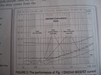
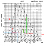
It works out to about 0.20 ΔmA per 200 ΔV between 200 V and 400 V. Usuing the usual formula:
Just Saying,
GoatGuy ✓
I'm jealous.
It works out to about 0.20 ΔmA per 200 ΔV between 200 V and 400 V. Usuing the usual formula:
ZDYN = ΔV / ΔI … in standard units
ZDYN ≈ 200 V ÷ 0.0002 A
ZDYN ≈ 1,000 kΩ
Its just an estimate, of course, from the graphs on the 10M90S datasheet, but “good enough”. ZDYN ≈ 200 V ÷ 0.0002 A
ZDYN ≈ 1,000 kΩ
Just Saying,
GoatGuy ✓
Lucky you… going to Kerry Ireland.
I'm jealous.
It works out to about 0.20 ΔmA per 200 ΔV between 200 V and 400 V. Usuing the usual formula:ZDYN = ΔV / ΔI … in standard unitsIts just an estimate, of course, from the graphs on the 10M90S datasheet, but “good enough”.
ZDYN ≈ 200 V ÷ 0.0002 A
ZDYN ≈ 1,000 kΩ
Just Saying,
GoatGuy ✓
Wow, 1 Meg. Many thanks. I'll buy you a beer or 2 next time I'm in the Bay Area. (Or maybe you would prefer a bottle of 20 year old Irish Whiskey).
Last edited:
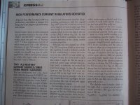
Walt Jung published a series of articles in AudioXpress where he measured the dynamic resistance of various different current sources (sinks). A 10M40 kind of sucks. A higher voltage version will require a larger silicone die (more capacitance) and perform more poorly at higher frequencies. If you want high dynamic resistance (and you do) you will have to switch to a cascode design. IXYS 2N50D2 on the bottom and 2N100D2 on top work well. K&K Audio sells inexpensive kits which make experimenting with CCS loads easy.
Walt Jung published a series of articles in AudioXpress where he measured the dynamic resistance of various different current sources (sinks). A 10M40 kind of sucks. A higher voltage version will require a larger silicone die (more capacitance) and perform more poorly at higher frequencies. If you want high dynamic resistance (and you do) you will have to switch to a cascode design. IXYS 2N50D2 on the bottom and 2N100D2 on top work well. K&K Audio sells inexpensive kits which make experimenting with CCS loads easy.
Thanks for that. I'll have a look.
If you want high dynamic resistance (and you do) you will have to switch to a cascode design
There can't be much wrong with 1Megaohm as a plate resistance.
I would like to thank everyone for the level of this thread and the forum in general. Coming here and read some posts is always inspiring. Thanks.
Yes, I agree totally. It's been a great help to me. All the diyAudio members are willing to give their time to help.
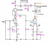
I have now successfully implemented the IXCP10M90S CCS as the plate load for the 6SN7 which drives the 300B. The result is phenomenal. Looks like the theory works out in practice - the dynamic resistance of the IXCP10M90S is certainly around 1MΩ at 6mA. I am using a 330K grid resistor on the 300B (yes, I know I'm living dangerously). This gives the 6SN7 a plate load of 248K - as near as dammit to a straight line.Lucky you… going to Kerry Ireland.
I'm jealous.
It works out to about 0.20 ΔmA per 200 ΔV between 200 V and 400 V. Usuing the usual formula:ZDYN = ΔV / ΔI … in standard unitsIts just an estimate, of course, from the graphs on the 10M90S datasheet, but “good enough”.
ZDYN ≈ 200 V ÷ 0.0002 A
ZDYN ≈ 1,000 kΩ
Just Saying,
GoatGuy ✓
I've measured the gain of the stage, and it is 19.8 - incredibly close to mu, but the really great aspects to this are the available voltage swing and linearity. I still need to fine-tune the bias and HT. I how have 2 Hammond 126C ISTs for use as doorstops. That was my first experience with ISTs, but I'm not dismissing them altogether - I can't see any need for them in this sort of simple 300B amplifier, now that I have been introduced to the world of Constant Current Sources.
To drive my 300Bs to a theoretical 8 Watts (7 Watts is more realistic), I need about 57 Volts RMS (80V Peak). With a gain of 20, the input to the 6SN7 driver would need to be 2.85 Volts RMS. This is well within the capabilities of all my pre-amps, and so the first half of the 6SN7 is now unused, just wasting heater Watts.
I've drawn out the operating conditions on the 6SN7 curves, and am also including the circuit of my new amplifier version in all its simplicity. It sounds just fine even with cheap Liuzhu 300Bs. Driver stage linearity enables the tonal characteristics of the 300Bs to be heard, without too much driver distortion diluting it.
Many thanks again for all your help everybody.
Attachments
Last edited:
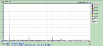
Definitely with you on preferring CCS on the SN7 over any IST. I get around 0.01% distortion over all signal levels from my SN7 stage, as long as you don't place burden on the stage (as you noted, a CCS and a grid resistor only). Our designs are quite different, but that first stage is critical. In my experience iron does not pair well with the SN7, no matter what I have tried from any manufacturer. Your 300B grids do have capacitance, which doesn't help; an intermediate stage is the ideal solution to that, but is fraught with its own challenges in implementing properly. You may also not require driving the output stage at 5W on a consistent basis, so it's fine as is.
Only been to Kerry once, would love to go back. As one who has lived in Wisconsin (the dairy state) for 40 years, I can attest to Ireland having better dairy.
Only been to Kerry once, would love to go back. As one who has lived in Wisconsin (the dairy state) for 40 years, I can attest to Ireland having better dairy.
Attachments
- Status
- This old topic is closed. If you want to reopen this topic, contact a moderator using the "Report Post" button.
- Home
- Amplifiers
- Tubes / Valves
- Using a CCS on an 6SN7; Plate vs Cathode