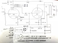
I'm assembling a small Chinese integrated amp kit using 6n2 and single ended 6p1 tubes (with silicon bridge rectifier). The schematic included uses pentode operation but I've seen variants (unfortunately the discussions are all Chinese) which appear to use triode operation.
Could someone please point me to exactly what changes need to be made in the attached schematic for triode mode? Do I have to be concerned with bias? Can I remove the 18k feedback resistor?
Could someone please point me to exactly what changes need to be made in the attached schematic for triode mode? Do I have to be concerned with bias? Can I remove the 18k feedback resistor?
Attachments
Unless you parallel 8 of them ")
I use 220R 1/2W almost exclusively. Excessive screen current will blow it saving the tube in extreme cases (speaker got unpluged while playing at loud volume or something like that).
You could use a switch to select between tetrode and triode mode, too.
I use 220R 1/2W almost exclusively. Excessive screen current will blow it saving the tube in extreme cases (speaker got unpluged while playing at loud volume or something like that).
You could use a switch to select between tetrode and triode mode, too.
Awesome, thanks a lot! Yeah I have a spare DPDT switch which should let me switch both L and R channels from tetrode to triode operation. Though I'm a little concerned running the wires to the switch at the back of the amp might induce hum or oscillation? Maybe shielding would be a good idea just in case...
Last edited:
Thanks I'm going to locate it around back along with the switch I added for selecting my add-on front-panel headphone jack. (A pair of 8 ohm/10w resistors are in parallel with the headphone outputs so when you switch to this setting the amp sees a reasonable load instead of just my 300 ohm headphones.)
A 220 Ohm 1/2 Watt resistor will stand 48mA all day long (but will be Very hot).
Normally, I make sure resistors are rated for 3 to 5 times the wattage that is applied, but if you are using the resistor for a fuse, you need the resistor to be Low power rated.
If the volume control was turned all the way up, and the loudspeaker was disconnected,
the screen current would be very high when the plate 'headed' toward 0V (maybe 50V).
But the duty cycle would be no more than 50%.
An extremely large Screen current could cause the 220 Ohm resistor to open.
Instead, I might be tempted to use one of those 60mA fuses in series with a 100 Ohm resistor to the screen. But the problem is, I would not trust that mini-fuse to really be open if the screen voltage is say 250, 350, 450V.
I would have to test a few of those fuses on the bench, to see if the metallization caused by opening with 450V applied did not sputter across the insides into a dead short.
I did use that 60mA fuse in a 300V application to protect the plate of a triode, when it blew, it did really open, it did not sputter 'short'.
Wavebourn,
Good points!
Walking around the amp 3 times clockwise is a good idea for all who do not get enough exercise (might have to walk 3 times counterclockwise for those who are down under).
Or, you can do 3 sets of 8 repetitions of lifting a powerful (heavy) tube amp.
Start with the simplest idea, try something else if that does not work.
Just a revision of my earlier statement (post # 10):
An extremely large screen current caused by turning the volume control all the way up in an attempt to hear music from the disconnected loudspeaker, might cause a 220 Ohm 1/2 Watt screen resistor to open, but not very likely.
Protection schemes do not always work as well as advertised.
A 1/2 Watt screen resistor is more likely to open if the Screen gets too hot, the screen wire sags, and causes a short to another tube element.
Last edited:
Results
I finished the kit last weekend with the mods described below. When I first switched it on I got a loud blast due to oscillation brought on by wiring the feedback resistor to the wrong leg of the transformer secondary -- causing positive feedback. Moving to the other leg fixed this problem.
I went ahead with adding a DPDT switch on the rear panel (using one of the extra pre-cut holes since I didn't bother wiring the 4 ohm taps) to select triode or tetrode operation, where the former connects left and right tube pins 2 to pins 1 via a 200 ohm resistor and the latter connects pins 2 to B+. Selecting triode mode gives 3 or 4 dB less gain than the tetrode setting.
I also added a headphone jack with a rear mounted DPDT switch to select headphone (paralleled with hard-wired 8-ohm resistor to ensure a suitable load for the output stage) or speaker operation. This caused a noticeable hum which turned out to be a ground loop with the metal-mount headphone jack I used initially. Swapping it for a plastic-insulated headphone jack eliminated this hum.
Last edited:
DIY instructions
For anyone who's interested here are my assembly/wiring notes for the 6N2+6P1 kit with headphone jack and triode/tetrode mods:
6N2+6P1 DIY single ended class A tube amp with headphone and triode mods - ralphgonz
For anyone who's interested here are my assembly/wiring notes for the 6N2+6P1 kit with headphone jack and triode/tetrode mods:
6N2+6P1 DIY single ended class A tube amp with headphone and triode mods - ralphgonz
- Status
- This old topic is closed. If you want to reopen this topic, contact a moderator using the "Report Post" button.
- Home
- Amplifiers
- Tubes / Valves
- Rewiring 6n2+6p1 SE pentode to triode?