So, after finding a nice resource showing how to extract values from the plate curve diagrams, I decided to largely ignore the charts in the Aikido Noval manual and work from the tube datasheets themselves.
Initially, I've decided to go with 6DJ8/6922s in both sections. I don't need that much gain, but I do have a small stockpile of these types so may as well use them.
If you'll indulge me, here's the values I've come up with after drawing the lines and doing the equations. Using Broskie's PS-21 board to produce 210V B+, which should drop to 180V through a 2K resistor on the Noval board input R12, putting 90v on each plate.
I decided to run the input section at 6mA and the output at 9mA ending up in the end with Rk of 330R and 200R respectively. R9 & R10 are 100K and 88K (well, 68K and 20K in series). This is the voltage divider referenced by Steve above? Sorry, I don't have the manual on me.
If I've done a semi-competent job with all this, it should be possible to sub the 6CG7 into the input section without changing any part values. It just won't be optimised for it.
Anybody spot any glaring issues?
Looks like a good starting point to me.
Don't be surprised if the current flow is a little less than you calculate (~10 -20%). It all depends on the tubes and their health. The resistors you've chosen for the first stage should be fairly close if you want to sub in a 6CG7.
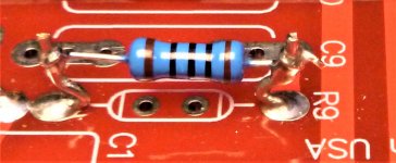
You might want to try this trick with your resistors in case you want to change them: (see picture).
Here's a trick you can try to see how well the sections of each tube match: Measure the voltage from cathode to plate on each section of a particular tube. Start with the input tube first (I'll explain why in a minute). Swap different tubes in and out (power off when swapping of course), until you get matching voltages between the "top" and "bottom" sections. A match of about a 5% or better should be possible if you have decent tubes.
Once the input tubes are "matched" do the same with the output tubes. The reason you do the inputs first is that an unbalanced input tube can make a well balanced output tube seem not so.
Steve
Don't be surprised if the current flow is a little less than you calculate (~10 -20%). It all depends on the tubes and their health. The resistors you've chosen for the first stage should be fairly close if you want to sub in a 6CG7.
You might want to try this trick with your resistors in case you want to change them: (see picture).
Here's a trick you can try to see how well the sections of each tube match: Measure the voltage from cathode to plate on each section of a particular tube. Start with the input tube first (I'll explain why in a minute). Swap different tubes in and out (power off when swapping of course), until you get matching voltages between the "top" and "bottom" sections. A match of about a 5% or better should be possible if you have decent tubes.
Once the input tubes are "matched" do the same with the output tubes. The reason you do the inputs first is that an unbalanced input tube can make a well balanced output tube seem not so.
Steve
Attachments
Update:
Thanks to the help received in this thread I now have a functioning power supply and Aikido board, which I have begun testing before hooking up the signal wiring, attenuator and selector switch. Pleasingly, it appears the current readings come very close to the values calculated. Measuring the voltages across the cathode resistors with a variety of 6DJ8/6922 tubes I get just under 6mA through the input section, and an average of 8.5mA on the output. One channel is slightly down compared to the other, but it's of no particular worry to me.
The process hasn't been smooth sailing however, as I had been getting some seemingly random values with different tube combinations, especially when inserted the output socket of one particular channel. An output tube that might read at 8.5mA in one channel (let's call this channel #2) could dip to as low as 7.5mA in the other channel (#1), even while paired with the same input tube each time. Some tubes presented this effect and some did not.
After spending three days chasing my own tail I was able to identify the source of the problem - but not the reason behind it. I thought you guys may have some insight.
I am using the newest version of John Broskie's Aikido Noval board. On the Broskie board B+ enters the first triode on pin 1 for channel #1 input and channel #2 output tubes. However, the channel #2 input and channel #1 output sockets receive B+ first to pin 6, which is where the problem emerges. I have performed controlled tests of six tubes in each position, and three of them suffer voltage drops when B+ is fed to pin 6 first, but measure fine when pin 1 is the first.
The most extreme example is one tube in a matched pair of Siemens early 1960's 6922s. One will measure 8.5mA in the output positon of both channels, whereas its partner will measure 9.5mA if feed B+ to pin 1 first, but will dip right down to 7.1mA if B+ is applied to pin 6 first. I should also point out that both triodes in each tube measure the same as each other each time, so it doesn't appear to be a matter of mis-matching there.
On the input the problem also occurs, but the voltage dip is much smaller. It is enough however, to produce a corresponding increase in the voltage/amperage of the output tube behind it.
Anyone got any clue about what's happening here? Sorry if my explanation is too convoluted. I can post a chart of all my readings in a couple of days.
It shouldn't matter if "top" triode is the first one (pins 1 to 3) or the second triode (pins 6 to 8). To see if the triodes in a particular tube are closely matched measure it first in the input tube position. An imbalance in an input tube might make the output tube look imbalanced even if it isn't.
If you measure the voltage drop across the cathode resistor, either top or bottom, you will measure an aggregate current flow through the tube. Both resistors will measure the same regardless to how well the sections match because the whole works ("top and "bottom" triodes and their resistors) are in series.
To determine triode matching in-circuit measure the voltage across pins 1 and 3 then compare it to the voltage measured across pins 6 and eight.
This is a procedure and explanation I wrote for another for another Aikido builder that should illustrate what I just described.
Balancing Aikido Input Tubes (V1 and V2):
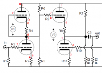
Refer to the attached schematic.
Short the inputs of if there is a volume pot on the input set it to minimum.
Ideally both the upper and lower halves of the input tubes V1 (and V2) have identical characteristics so that there is half the supply voltage at points B & E. If you don’t have half (or thereabouts) the supply voltage at point E then the output tube V3 (and V4) is not working optimally and its static current draw and the balance between the top and bottom halves will be affected.
Resistors R5 and R6 supply a reference voltage (I think) but as these are 1 meg resistors they carry very little current and won’t “pull” a lopsided input tube into line.
At first I was measuring the cathode voltage from ground to point A. The same voltage will also be measured from points B to C as the two triodes and the two (R2 & R4) resistors are all in series. Uneven triodes cannot be detected this way though you will get an idea measuring from point B to ground which should be half of the B+ voltage.
I prefer to measure the voltage drops across the triodes themselves. By comparing the voltage measured between points A and B to the voltage between points C and D I get a true idea of balance (or not) between the two triodes in any one tube. The voltage measured from ground to point A helps me match pairs of tubes once I’ve established each one has decent balance between its sections.
The devil’s own tube tester, my Eico 666, is not entirely reliable in this regard, big surprise huh?
I’ve seen tubes that tested reasonably well for balance on the 666 have a considerable imbalance in the Aikido circuit. Sometimes the Δ voltage between the two sections is as high as 10 volts, granted this one didn’t test very good on the 666. But I have seen tubes that had sections that measured identically on the 666 have a 4 volt Δ and others with a 1 volt or less Δ.
Good luck, Steve
If you measure the voltage drop across the cathode resistor, either top or bottom, you will measure an aggregate current flow through the tube. Both resistors will measure the same regardless to how well the sections match because the whole works ("top and "bottom" triodes and their resistors) are in series.
To determine triode matching in-circuit measure the voltage across pins 1 and 3 then compare it to the voltage measured across pins 6 and eight.
This is a procedure and explanation I wrote for another for another Aikido builder that should illustrate what I just described.
Balancing Aikido Input Tubes (V1 and V2):
Refer to the attached schematic.
Short the inputs of if there is a volume pot on the input set it to minimum.
Ideally both the upper and lower halves of the input tubes V1 (and V2) have identical characteristics so that there is half the supply voltage at points B & E. If you don’t have half (or thereabouts) the supply voltage at point E then the output tube V3 (and V4) is not working optimally and its static current draw and the balance between the top and bottom halves will be affected.
Resistors R5 and R6 supply a reference voltage (I think) but as these are 1 meg resistors they carry very little current and won’t “pull” a lopsided input tube into line.
At first I was measuring the cathode voltage from ground to point A. The same voltage will also be measured from points B to C as the two triodes and the two (R2 & R4) resistors are all in series. Uneven triodes cannot be detected this way though you will get an idea measuring from point B to ground which should be half of the B+ voltage.
I prefer to measure the voltage drops across the triodes themselves. By comparing the voltage measured between points A and B to the voltage between points C and D I get a true idea of balance (or not) between the two triodes in any one tube. The voltage measured from ground to point A helps me match pairs of tubes once I’ve established each one has decent balance between its sections.
The devil’s own tube tester, my Eico 666, is not entirely reliable in this regard, big surprise huh?
I’ve seen tubes that tested reasonably well for balance on the 666 have a considerable imbalance in the Aikido circuit. Sometimes the Δ voltage between the two sections is as high as 10 volts, granted this one didn’t test very good on the 666. But I have seen tubes that had sections that measured identically on the 666 have a 4 volt Δ and others with a 1 volt or less Δ.
Good luck, Steve
Attachments
Thanks Steve, I think you have answered my question entirely. I didn't realise the current across the cathode resistors would measure as an aggregate.
I had also taken readings across the actual triodes, but didn't quite know if I was interpreting them properly. But I do recall some triodes being very close and others not.
Bit of a shame some of these expensive matched pairs aren't as matched as one might hope.
I had also taken readings across the actual triodes, but didn't quite know if I was interpreting them properly. But I do recall some triodes being very close and others not.
Bit of a shame some of these expensive matched pairs aren't as matched as one might hope.
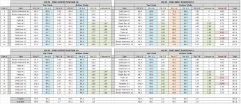
I’m back with a table of values measured over the last couple of days, thanks to Steve’s guidance. It’s quite a bit of info to parse (and I’m not sure I have the skills to do so) but for me there’s a few interesting things worth noting.
1. It appears the oddball readings I was initially getting is likely due to the 18-19 volt mismatch between the two triodes in Siemens #1. Looking at the rest of the measurements, I think I’ll be pleased to get anything under a 5V difference in any tube.
2. The voltage drop across the cathode resistors appear to match the bottom triodes grid-to-cathode voltages for the output sections, and the top triodes grid-to-cathode voltages for the input sections. Not sure if that’s anything particularly meaningful.
3. For both input positions the plate-to-grid voltage shows a signifcant dip, which I’m assuming is due to grid stopper R2 messing with the measurement. However, it stills seems odd for the difference between V1 & V2 to be so great.
4. The most closely matched tube pairings look to be the new production tubes. The Gold Lions were purchased from Jim McShane, who seems to have done a terrific matching job. Amusingly, the bog-standard Electro Harmonix are the only tubes that I didn’t buy as a matched pair. They draw more current than the other tubes, which I expect is because they are in actuality 6N23P’s?
Anyway, I think I’m finished prodding this thing. Onto the signal wire connections (unless anyone can see a glaring problem?).
Attachments
Lotsa measurements!
Conclusions from all your measurements?
The Aikido direct couples (no capacitor) between the input tube (gain stage) and the output tube (cathode follower). So any mismatch between the triodes in any one tube will induce a mismatch in the other tube in the same channel.
Once you find two low delta tubes in the same channel (measuring cathode to anode) these will become your references. You can then use the lowest delta tube(s) (I would suggest the input tube position) to "test" the remainder of your tubes in the output tube position.
If a tube shows a high delta in the "test" position (output) it will likely pull the reference tube into imbalance too.
Once you've culled the imbalanced tubes the hard part begins: Deciding which of the balanced tubes sounds the "best".
See links below to a tube shootout I did for WallofSound .ca. It's far from thorough but it might give you a starting point. Generally speaking, I've found that the input tube will have a larger bearing on sonics.
Vacuum Tube Shootout: 6DJ8 types (part 1) | Wall of Sound | Audio and Music Reviews
Vacuum Tube Shootout: 6DJ8 types (part 2) | Wall of Sound | Audio and Music Reviews
Be sure to read the comments. Some agree and some think I'm full of crap.
Steve
Thanks again Steve. I didn't much consider the output tube affect on the input, so I'll have to perform some more measurements when I can find the energy for them again.
I have an ANK kit DAC and an integrated amp that both use the 6DJ8 family of tubes, so I am already familiar with your article. For what it's worth, I mostly agree with you") .
.
It looks like you're also the author of the Aikido phono stage build on WallofSound? That guide has been an invaluable resource for my build - most particularly in regard to chassis layout, preparation and grounding.
I have an ANK kit DAC and an integrated amp that both use the 6DJ8 family of tubes, so I am already familiar with your article. For what it's worth, I mostly agree with you
.It looks like you're also the author of the Aikido phono stage build on WallofSound? That guide has been an invaluable resource for my build - most particularly in regard to chassis layout, preparation and grounding.
- Status
- This old topic is closed. If you want to reopen this topic, contact a moderator using the "Report Post" button.
- Home
- Amplifiers
- Tubes / Valves
- Aikido cathode resistors