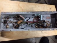
I spent my day pulling this el84SE Magnovox amp and pre amp out of the console. It played 3 years ago but did have a power tube that was cracked at the base. I love the simplicity of this amp, definitely getting cleaned, re capped and a long listen to. Same with the pre amp. I have no idea what year or model this is.
Attachments
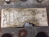
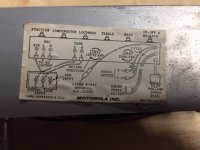
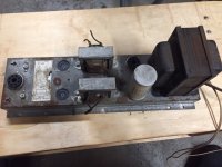
It's Motorola, not Magnavox.
FWIW, I'd focus on rebuilding the amp. The way the 2 chassis are separated is out of the ordinary. The voltage amplifiers driving the O/P tubes are on the control chassis, not the power chassis, and (IMO) that's not good. There's no NFB to the voltage gain blocks and a fairly high signal level is being carried by the cabling between the 2 chassis. The power trafo seems substantial, but the O/P trafos lack heft. Another sign of cheap construction is the use of phenolic wafer sockets for the 6BQ5 O/P tubes. That trash should go.
To extract maximum bass extension from the O/P trafos, I suggest reconstruction more or less along the lines of the DECWARE SE84, with triode wired O/P tubes that yield approx. 2 WPC. Obviously, high efficiency speakers are needed. Might as well take advantage of the Octal socket currently used for "preamp" power and put a 6SN7 there to serve in the voltage amplification role.
Can't beat Cryo-treated Jupiter Beeswax film-caps for a sweet sound that is not at all sticky.
")
I would not worry about the wafer sockets, just give them a spray and push the pins in and out.
I will look into the suggestions after I get it cleaned up and take some measurements.
Hopefully, those numbers will improve the thinking mere visual observations drive.
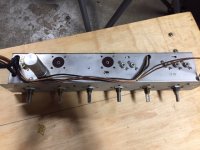
FWIW, I currently like the power trafo and am OK with the power chassis. The underside photo clearly shows the use of the chassis as a signal carrier.
Definitely add a bus or star grounding scheme. If this replacement O/P trafo fits mechanically, things get (IMO) truly interesting, as 5 HIFI WPC channel become feasible. An inexpensive Chinese 5AR4 as the rectifier gains a few extra B+ V., without increasing stress on the power trafo's 5 V. filament winding. 7189 equivalent Russian 6Π14Π-EB (6p14p-ev), AKA EL84M, O/P tubes safely exploit those extra B+ V. Set the new "finals" up in UL mode, for fidelity's sake. A 6SL7 takes care of voltage amplification, for both channels. DC couple ZVN0545A source followers to the 6SL7 plates to ensure UL mode CMiller can't cause trouble. A modest amount of GNFB yields a decent damping factor and linearizes the new O/P "iron".
BTW, the rust stains can be dealt with by applying lemon juice, followed by a water rinse, and an alcohol dry.
I checked all the tubes, all good except for a broken el84 so I replaced them with a new pair and fired it up yesterday with a dim bub tester. Short started showing up at 80 volts, went ahead and upped the voltage to 120, ran my MP3 player to the pre amp and listened to it while I was doing laundry. Also gave it a listen at 110 volts, I think it sounded better.
(not surprising considering its age and when it was designed)
Even with really crappy speakers it was plenty loud enough. Guess I'll start looking for 40UF 350 volt capacitors, need 5 of them, 4 for the amp and 1 for the pre amp.
After 2 hours the transformer was still room temperature.
(not surprising considering its age and when it was designed)
Even with really crappy speakers it was plenty loud enough. Guess I'll start looking for 40UF 350 volt capacitors, need 5 of them, 4 for the amp and 1 for the pre amp.
After 2 hours the transformer was still room temperature.
Last edited:
What's the diameter of the quad section part? You can go up in WVDC, without worry. Jim McShane shows a triple 40 μF./525 WVDC twistlok that might be combined with this, on the underside, to take care of that 4X40 μF.
Disconnect the 40 μF. twistlok on the control chassis and leave it for show. Another of those 39 μF. parts, on the underside, would take up the electrical duties.
Disconnect the 40 μF. twistlok on the control chassis and leave it for show. Another of those 39 μF. parts, on the underside, would take up the electrical duties.
- Status
- This old topic is closed. If you want to reopen this topic, contact a moderator using the "Report Post" button.
- Home
- Amplifiers
- Tubes / Valves
- SE Magnavox EL84