Hi all!
As per title newbe just finish his build an SE with KT88 All seems fine the amp sounds very good to me. However There is little hum same in both channel but at very acceptable level this is more pronounced when the input jack are disconnected while almost disappear when the source is connected so I could leave with that. In any case any lead to follow to improve?
Also There is one thing I found very strange when the amp is on all voltage are just as they should be and as said it sound ok but when I power off the amp the voltage in the circuit drop quite fast while I understand the caps should retain the charge for long time Do you think this is a problem or could it be normal?
Any advice appreciated and thank you
There is little hum same in both channel but at very acceptable level this is more pronounced
when the input jack are disconnected while almost disappear when the source is connected.
when I power off the amp the voltage in the circuit drop quite fast
Post some photos, possibly wire routing is causing the hum problem.
The rapid drop in B+ on turnoff is normal.
Hi all!
when the amp is on all voltage are just as they should be and as said it sound ok but when I power off the amp the voltage in the circuit drop quite fast while I understand the caps should retain the charge for long time
Do you think this is a problem or could it be normal?
It is normal for power amp. Those KT88 are still warm and they will drain the store charge quickly It is when something not functioning properly that they can become dangerous for a long time. You should still put in leak resistors for those cases?
Hi guys
Thanks for the replay.
To be honest I was more concerned about the rapid voltage drop at power off than the hum problem and I am glad that is "normal". The hum was something that I already accounted for at beginning of the project considering the number of components used and the fact that the idea was to use a full set of industrial (not audio) trafo.Sure can be done better but hey...is my first project -)
I made that way because I wanted a learning project. I want to experiment a range of unusual solution as Para feed connection and ultra path for example.
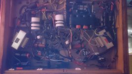
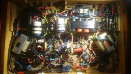
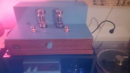
Anyway attached some pictures of the finished product. Nothing to be proud of but it sounds well and I am happy.
thank you
Thanks for the replay.
To be honest I was more concerned about the rapid voltage drop at power off than the hum problem and I am glad that is "normal". The hum was something that I already accounted for at beginning of the project considering the number of components used and the fact that the idea was to use a full set of industrial (not audio) trafo.Sure can be done better but hey...is my first project -)
I made that way because I wanted a learning project. I want to experiment a range of unusual solution as Para feed connection and ultra path for example.
Anyway attached some pictures of the finished product. Nothing to be proud of but it sounds well and I am happy.
thank you
Attachments
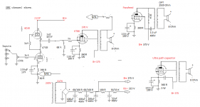
Hi here is the schematic
Note that:
I did not invent anythingh just tried to make use of what is available on the web for the purpose of my excercise
Some of the technique i used i.e.parafeed connection and ultrapath capacitor may not be necessary if using standard good quality audio transformer (the build would be more easy and probably the end result better)
In my case using standar electrical toroidal trasformer i measure with no NFB a response from 30Hz up to 18Kz within 3db in triode connection while in pentode the bandwith is more limited on the bass
with accurate use of NFB the ampli is flat from 25 Hz to more than 20Kz in pentode and even better in triode (howewr i like the pentode mode more
) Sound is full and warm with powerfull bass and clear high may be i would like litle more details but yes nice sound to me.
Overall i am happy but i aknowledge the fact that i have very limited knowledge on tube amp build and actually i would apreciate any comment/advice
Attachments
> rapid voltage drop at power off
When the KT88s are hot they flow about 100mA each, 200mA for two. At 375V, this acts-like 375V/0.2A or 1872 Ohms. You have about 300uFd of main supply reservoir. 1875*300EE-6 is 0.56 seconds. "If" the tubes stay hot this long, voltage will drop by 63%, to 0.37X, or to 139V; to 51V in 1.12 Seconds.
While the cathodes will cool in this time, the '88 has much reserve, and 100mA is not a huge current in '88s. I would expect 375V to fall far below 100V in 1 second.
That's if the '88s were/are sucking current. If a wire falls off, no current. Your small-tube may still suck but much less, and won't pull down 300uFd much before its cathode cools. If all the B+ loads fall-off, there is only the caps' leakage, which is rated for maybe 6 minutes, and could be even slower.
According to your schematic, you have a Heater to Cathode voltage rating problem:
6DJ8 unit 1, pins 6, 7, 8, are rated 50 Volts average.
6DJ8 unit 2, pins 1, 2, 3, are rated -130V average, -150V peak.
Your 6DJ8 SRPP is wired wrong. Unit 1 and Unit 2 need to be swapped, in order not to exceed the maximum heater to cathode voltage ratings.
6DJ8 unit 1, pins 6, 7, 8, are rated 50 Volts average.
6DJ8 unit 2, pins 1, 2, 3, are rated -130V average, -150V peak.
Your 6DJ8 SRPP is wired wrong. Unit 1 and Unit 2 need to be swapped, in order not to exceed the maximum heater to cathode voltage ratings.
Yes i elevated the heaters because of this problem.It is not on the schematic but if you see the pictures low on the right there is a voltage divider with resistor and a small cap connected to the transformer heater center tap.This elevate 80/90V .This should solve the problem (i think)
Ok: Big improvment... I had the heaters at 6.8V because the dedicate industrial trafo is a kind of beast (that is what i found available in my working place -)) So i lower it to 5.9 by means of a resistor. Well hum away!! I also put two good quality poly cap as by pass on the two electrolitics cap suplying the 6DJ8 anode.The difference is minimal but i think soundis litle more details and more tri dimensional. Now is really time to listen some music Thank you all for all your suggestion.
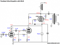
Hi the right schematic is the one I post first .Only the parafeed connection is made differently. Hence I post this second one to show how the parafeed is connected sorry if this created confusion. Ref the heater elevation .I am not able to have a technical discussion on it is above my level. However: The pre section is not my design it is basically a forewatt line pre amp by Bruce Heran. The original version use ECC802 but that was not sufficient to drive the KT88 so after consultation with Bruce I change to 6DJ8 with minimal modification Bruce recommend to elevate the heater (see below)Your schematic in post # 13 is completely different. It does not need the heaters to be elevated.
"The heaters must not be connected to the same ground as the signal, B+ or chassis. They need to float or tube failure may occur. The only connection of the heater circuit to the rest of the circuitry is a "bias" tap. This is developed from the main B+ supply and is about 1/3 the B+. No current flows through this connection (perhaps a tiny bit of leakage). It only establishes a reference for the heaters so that the difference between the heaters and any of the cathodes is less than 100 volts. One quirk of SRPP and other "totem pole" circuit configurations is that one of the cathodes is elevated quite a bit above ground.
In a SRPP the cathode on the upper triode has a voltage potential of roughly 1/2 the applied B+. So with 215-225 V on the anode the cathode is over 100 V. During start up this value is actually 1/2 the full B+ (of about 275 V). This value exceeds the tube rating for heater to cathode voltage and will result in tube failure. Perhaps this will not occur immediately, but it will as the tube ages. I have had this happen. Not a good thing. It usually results a huge spike in the output that could be catastrophic further down the audio chain."
12AU7s were rated for +100 and -200V heater to cathode. ECC802 was approximately a 12AU7 equivalent, but +/- 100V heater to cathode.
6DJ8, 6922, and ECC88 were rated for 50V, 60V, 90V, 120V heater to cathode, depending on + or -, and the manufacturer of the tube. The early 6DJ8 had a higher heater to cathode voltage rating on One of the two triodes.
Changing from a 12AU7 or ECC802 to a 6DJ8 just to have more gain, does have some serious heater consequences.
There is a DC component of the heater to cathode voltage, and for the top triode in an SRPP, there is an AC component of the heater to cathode voltage. That AC component is the largest swing that is required to drive the next stage. Take a 300B for example, with 60, 70, 80, or even 90V bias. The SRPP will have to drive from +/- 60 to +/- 90Volts according to that bias.
If you use a 6DJ8, and have a Stereo amp on one chassis, you should use two 6DJ8s. A. One 6DJ8 for left and right Bottom triodes of the SRPP stages, and have the filaments at or near ground. B. Use another filament winding for a second 6DJ8 for the left and right Top triodes of the SRPP, and elevate that filament at or near to the cathode(s) voltage of the top tube triodes.
Now you know one of the reasons I do not use SRPP any more. I prefer using a triode that has a current source in the plate, i.e. a 900V IXYS part. It has low distortion and good signal swing, and eliminates the dual filament voltage supply problem.
Thanks for the detailed explanation.Alot to learn here. Googling around it appear that all you say is very correct and a proper SRPP should be done the way you say (do you have any schematic for such configuration?)On the other end to do that would require to re build the pre section... while the solution implemented already seems to be also popular (so i think not completely wrong or not?)
In any case if i leave like that what could happen, would that affect the sound or may lead to breack down?Bearing in mind the amp has been already working fine for almost one year (yes that the time that toke me to tune it as i like!!) also someone mentioned in previous posts a leak resistor what is that and were should be located.
In any case if i leave like that what could happen, would that affect the sound or may lead to breack down?Bearing in mind the amp has been already working fine for almost one year (yes that the time that toke me to tune it as i like!!) also someone mentioned in previous posts a leak resistor what is that and were should be located.
Many SRPP stages that exceed the filament to cathode voltage ratings, and many Concertina phase invertor stages that exceed the filament to cathode voltage ratings of the tubes work well for many years.
Some of those circuits do not work well, either in the beginning, or as time goes on.
Depends on the tube type, manufacturer, circuit voltages, etc.
What if you can no longer find a particular manufacturer's tube that is more robust?
Why gamble?
Stay within the tube maximum ratings. If that requires another 6.3V winding, and a resistive voltage divider, plus a bypass capacitor, and the voltage divided from the B+, in order to be within the tube's maximum ratings, I recommend doing that.
"You should make things as simple as possible, but no simpler" - Sometimes attributed to Albert Einstein, but the origin of the quote, and exact wording is questioned.
Last edited:
- Status
- This old topic is closed. If you want to reopen this topic, contact a moderator using the "Report Post" button.
- Home
- Amplifiers
- Tubes / Valves
- little help x newbe