Hello, I need help resizing a crossover scheme to be used for the combination between the power mp of the ESL63 panels and the power amp of a ripole subwoofer (jazzman scheme) for the last octave ie 20-120 Hz. This scheme is used by shackmann to do so but uses some hard-to-find tubes (12ay7)
I would have the request in the limit of availability to suggest another tube, possibly from the ecc range and a spice sim..
Thank you in advance.
I would have the request in the limit of availability to suggest another tube, possibly from the ecc range and a spice sim..
Thank you in advance.
Attachments
12ay7 is not rare or hard to find but new ones are pricey Electro-Harmonix 12AY7 EH / 6072A Vacuum Tube: Amazon.ca: Home & Kitchen
Yes you are right, but do you think that I can simly repace 12AY7 with a 12AX7? Shall be the same load line...or?The cathode impedance is not critical. It will stay near to 33k set by the load resistor, not the valve.
Thanks, I know, but I'd prefer NOS not russian ones, to be honest12ay7 is not rare or hard to find but new ones are pricey Electro-Harmonix 12AY7 EH / 6072A Vacuum Tube: Amazon.ca: Home & Kitchen
Is the work impedance of the net. If you change it you change the frequency of the filterThe cathode impedance is not critical. It will stay near to 33k set by the load resistor, not the valve.
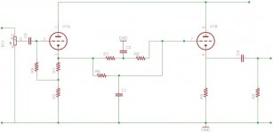
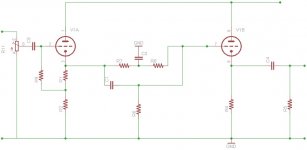
I done one similar as topolgy with 6922, the Zout is around 350 ohm, fine.
And the Vdc around 220. With 6 mA each section of tube.
The picture are for 6 dB mut simply is possible to have 12 dB, same way of the old circuit
Walter
And the Vdc around 220. With 6 mA each section of tube.
The picture are for 6 dB mut simply is possible to have 12 dB, same way of the old circuit
Walter
Attachments
The cathode impedance will be nowhere near 33k. It will be approximately 1/gm, with 33k in parallel. There will be a small change in filter behaviour when changing the valve, but the original circuit appears to have been designed assuming that the cathode impedance will be zero so some error has already been accepted.JonSnell Electronic said:The cathode impedance is not critical. It will stay near to 33k set by the load resistor, not the valve.
Thanks, but there is no way to calculate (at least theoreticaly) for the whole circuit? Something like a spice sim or something. I see difficult to find the 12AY7 and verry expencive but I have plenty of ecc83 or ecc88.
To me it seams to result some 14K (25kII33k)
Regards,
To me it seams to result some 14K (25kII33k)
Regards,
I can't see anything 14k in that circuit. As I said, cathode impedance is roughly 1/gm with the cathode resistance in parallel. gm will be around 1-3mA/V (depends on bias), so cathode impedance will be in the region of 300R-1k. This will affect the filter network, but as this does not appear to be a precision design it won't matter.
You can use the ECC83 in this circuit. As a wild guess, use something around 68k-100k instead of 33k and 1-1.5k instead of 227R.
You can use the ECC83 in this circuit. As a wild guess, use something around 68k-100k instead of 33k and 1-1.5k instead of 227R.
There is a very good article written by Brian Clark "Active Crossover Network Design Manual" that in 26 pages gives a good orientation with calculations, parts list for a final design etc (He used the 6922). It's copyrighted (1983) and I don't know if Brian is still around or not and won't post without his OK if he's still in the game. If anybody knows him could you PM contact info? I'll ask if it's cool to post the article here.
The designer assumed the tube's cathode impedance is "nearly zero", much less than the 4,700 Ohms of the first stage of the filter.
Relative to 4,700r, almost any triode will be about the same cathode impedance. 12AY7 was sold as "low noise", but 12AX7 12AT7 12AU7 and their EU similars will all work here.
The design is not how most modern designers would do it. The filter corner is very broad. (Which is another reason the exact tube hardly matters.)
You need output DC-block caps!
Just in case anyone hasn't spotted it, the design we are discussing achieves its nominal 800Hz crossover by using two low Q 3rd-order networks which are each merely cascaded unbuffered first-order networks. They are to a certain extent isolated from each other by means of raising the impedance at each stage. As PRR says, the filter corner will be broad.
The 800Hz corner frequency is obtained by choosing high-pass CR for 500Hz and low-pass CR for 1350Hz; those with calculators can check that 800 is approximately the geometric mean of 500 and 1350. Any attempt to redesign for another frequency F Hz by choosing CR for F Hz will lead to a significant dip in overall response around F Hz. Instead, you need to follow the instructions on the circuit and scale from the current values.
The 800Hz corner frequency is obtained by choosing high-pass CR for 500Hz and low-pass CR for 1350Hz; those with calculators can check that 800 is approximately the geometric mean of 500 and 1350. Any attempt to redesign for another frequency F Hz by choosing CR for F Hz will lead to a significant dip in overall response around F Hz. Instead, you need to follow the instructions on the circuit and scale from the current values.
- Status
- This old topic is closed. If you want to reopen this topic, contact a moderator using the "Report Post" button.
- Home
- Amplifiers
- Tubes / Valves
- Building a valve crossover