x 6A3
6H6/6N6 russian
Regarding the IT I can't understand why we spent lot of time and money to have a stuff that must be, of course, with the same quality of OT (maybe better). In additon it must have a descending ratio (= low Zout) so in this way it is possible to drive the grid of 300B at the best, specially if we decide to reach A2 region so the swing on primary must be very high with a low distortion ( very hard!!!).
So we have a first gain stage, the second gain stage but the IT ( on anode or parafeed) reduce the signal then the 300B that amplify it again and an OT that reduce again!!!!!!!!
Is it normal?
The 300B need semplicity due the beatiful linearity. This is may opinion One example:
why not E88C
post 58 and 60
Regarding CF I will post later.
Walter
So we have a first gain stage, the second gain stage but the IT ( on anode or parafeed) reduce the signal then the 300B that amplify it again and an OT that reduce again!!!!!!!!
Is it normal?
Walter
The combined gain of two cascaded 6SN7's with bypassed cathode resistors is about 200 if things are done right. Using 2:1 step down IT with just 1V peak at the input you get 200V peak-to-peak. I think that's more than enough and in many cases, with a lot a modern sources, you can also put a volume potentiometer without the need of a preamplifier. The total gain of the amp is not a problem at all.
The problem with a 2:1 IT would be the the enormous voltage swing required to the driver even before considering class A2 operation!! I don't know any driver that can give undistorted 400V peak-to-peak with approx. 300-350V anode voltage. So the 2:1 IT is not a good idea, IMHO, unless you want to make a more complicated, expensive power supply and likely use more expensive driver tubes.
My suggestion of using the IT is not for class A2 but for the Sun Audio style circuit which also uses cathode bias for the 300B. Simply the IT replaces the 27K anode resistor and then just tweaking some values to optimise the operative conditions. Moreover a bifilar 1:1 IT would be the best choice for excellent bandwidth. It's not difficult to get 120-140H for 10mA plate current.
The cathode follower is a better solution class A2. No question about it.
Last edited:
Actually, if one doesn't want to spend a lot money for high quality bifilar IT's can use the LL1660/10mA in REVERSED Alt S connection. High frequency response will not be as good but still 40KHz @-1dB is not bad at all.
Reversed ALT S means 4.5:4 which is slightly step-down. The recommended primary DC current will be 10*(4/4.5)=9 mA and the primary inductance will be 130*(4.5/4)^2=164H. The 6SN7 running at 250-300V 8-9 mA will have some 7-8K plate resistance and so would be ok, in my experience. No significant peaking at high frequency and good bass response.
Running at 9 mA anode current the LL1660 in reversed ALT S will be capable of 220V rms at 30Hz. At 20Hz that would be 148 Vrms. That's 2x of what is needed to drive a 300B in the worst case.
A driver tube with a 3k rp, and a 1:1 interstage coupling, drives the 300B with 3k. Suppose the 300B grid is driven into A2, and that the 300B grid is about 1k with that signal level. The impedance one way is 750 Ohms, and the other way is 3k; the ratio is 4:1. That sets the Short overload recovery time.
A driver with 3k rp, and a (unusually large) 1uF driving 100k RC coupling 300B is far different. 3k driving 1k grid, then 3k driving 100k. The impedance one way is 4k, and the other way is 100k; the ratio is 25:1. That sets the Long overload recovery time.
However, the best way to deal with overload recovery time is to set the volume control to prevent overload and clipping. Need more sound but without overload or clipping, then get a more powerful amp.
I like the square wave response and frequency response of RC coupling, versus the square wave response and frequency response of interstage coupling of the interstage transformers I have been able to afford. Also, most RC coupling is less sensitive to magnetic hum fields than interstage.
Last edited:
I believe this thread is about 300b SE not pushpull. ...
If anything to be corrected in the first post schematic please tell me.
I don't think they are listening.
One issue that I missed in post no. 8 was that the schematic does not show a centre tapped winding or alternatively a twin resistor network for earthing the heater supply of the 6SN7 twin triode. Post #3 correctly brought this point up and this may be the main reason for rhythmsandys' original query.
Last edited:
I wrote that for the best results is better to use the 6SN7 as gain stage and 5687 for driver. Rhytmsandy has already a 6SN7 with some changes and one 5687 each channel can resolve at the best, in my opinion. The original diagram is, as quality, at low level, always my opinion
Walter
Walter
The original diagram is, as quality, at low level, always my opinion
Walter
I agree. It is acceptable with 2A3, works better with pentodes/UL which do not required large swing and it's a poor circuit with 300B. Easy to do better.
Regarding the IT I am not sure that the theory of 45 on trafos can be enough for a good driving of 300B. With 1:1 ratio in every case the Zout of the stage is too high, in addition we can check also the falling of impedance a low and high frequency and, at last, if the signal takes the grid in a positive grid so in this case the Zout of the driver stage collapse with great consequence.
Also for CF, in my opinion, is not a good idea to use this circuit because to reach a good swing at low distortion is easy to use two previous gain stage so the total are three and the last (CF) has a loss of 1 db (around). If the signal take the grid of 300B in a positive region the current flow because the input impedance of 300 that becoming low (in a non linear way) related directly with the amplitude.
In this way the working point of CF is moving dinamically and this is not good.
If I use the SRPP like the Audio note Kit 1 the Zout is low as the CF ( less or more) almost comparable and the changing of the working point is the same issue also fot this configuration but I have one stage less and this is good!")
Always my opnion
Walter
Also for CF, in my opinion, is not a good idea to use this circuit because to reach a good swing at low distortion is easy to use two previous gain stage so the total are three and the last (CF) has a loss of 1 db (around). If the signal take the grid of 300B in a positive region the current flow because the input impedance of 300 that becoming low (in a non linear way) related directly with the amplitude.
In this way the working point of CF is moving dinamically and this is not good.
If I use the SRPP like the Audio note Kit 1 the Zout is low as the CF ( less or more) almost comparable and the changing of the working point is the same issue also fot this configuration but I have one stage less and this is good!
Always my opnion
Walter
Last edited:
I don't think you will get a proper swing with a low distortion with a single pentode stage.
Otherwise please let me know the type and working point and I will test on my lab then I can post the results.
I used two E88C in SRPP with a good results but the sensitivity is not high and the Zout is resonable. The sound is also good.
Walter
Otherwise please let me know the type and working point and I will test on my lab then I can post the results.
I used two E88C in SRPP with a good results but the sensitivity is not high and the Zout is resonable. The sound is also good.
Walter
I don't think you will get a proper swing with a low distortion with a single pentode stage.
Trioded D3a, CCS, 70V RMS (198Vpp).
Attachments
The LL1660 in reversed ALT S configuration has 164H which means more than 20K at 20Hz. With 9mA current at 20Hz the driver can swing a maximum voltage V=4.44*f*L*I=131 Vrms! Taking into account the small step-down ratio this becomes 116 Vrms. You need at worst 70V rms....Regarding the IT I am not sure that the theory of 45 on trafos can be enough for a good driving of 300B. With 1:1 ratio in every case the Zout of the stage is too high, in addition we can check also the falling of impedance a low and high frequency and, at last, if the signal takes the grid in a positive grid so in this case the Zout of the driver stage collapse with great consequence.
I think most output transformers cause a lot more distortion. At 30Hz distortion becomes really small and still much better than output stage. High frequency is more variable. Anyway if one wants the best can buy a bifilar Monolith Magnetics that has 100KHz bandwidth with 8K source impedance of the 6SN7.
Regarding the grid current this is a SOFT clipping limit. Especially if one uses cathode bias. Zero blocking distortion. You don't have that with RC coupling.
You need an update Walter...forget the local experimental stuff you use.
What? The grid current doesn't go through the cathode resistor. It goes straight into the grid! It doesn't move...otherwise your power supply is not good enough.In this way the working point of CF is moving dinamically and this is not good.
Sorry Walter but the mu-follwer is worst of the three. It only has low distortion in very specific conditions. Low Zout is not enough. If the load changes from the optimal value distortion can be the same as a simple common cathode. And it will change when grid current start to flow....If I use the SRPP like the Audio note Kit 1 the Zout is low as the CF ( less or more) almost comparable and the changing of the working point is the same issue also fot this configuration but I have one stage less and this is good!
Always my opnion
Walter
Last edited:
Just some opinion
About the IT trafo, the details from Lundhal can be fine but the main problem still exist, the Zout is too high, that's all. And this is not good in general and also around positive grid region ( in case). In addition the number by 45 are theoretically because, as usual, is better to have the right test done mainly at low and high frequency.
If I want a reasonable low Zout with IT, I must use a different tube as 6BL7 that has 2100 ohm of Rp and more current, in this case following the sheet from Lundhal the max rms voltage is 53 volt, or 6H30 ( the gain is not so high). Or 5687, or 7044 (very good also for mu)
Regarding the CF the load line is changin if the load goes low, same for SRPP; if it is high enough it stay as designed, if it goes low the CF change its performances in wrong way. Regarding the versus of the current, of course it goes through the grid. The power supply is not involved.
I spoke about two topology; I agree about the mu-follower.
Walter
Zout too high for what? It's not to high for the transformer and it is not too high for driving the 300B in class A1. The values of the transformer are not theorical because I have the LL1660. You need to explain why do you need lower Zout. Why? There is no class A2 operation and actually using cathode bias the higher Zout helps with softer clipping!
You have absolutely NO idea how the cathode follower works. The load line changes only along the high current-low voltage area where the tube is very very linear. Especially the cathode follower. Very low distortion indeed. So distortion is only proportional to the Zout of the CF. The lower the better.
This is not true for the SRPP or Mu-follower because they do not behave like a single stage and distortion is strongly dependent on the load. Moreover you have RC coupling while the cathode follower is DC coupled. Sorry Walter but you are the one inventing theories.
Just to add some info on the CF argument (in case we can open a thread) I post some tests.
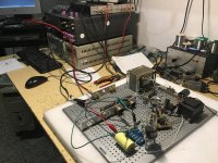
First of all today I have quickly prepared a CF circuit with a 6SN7 soviet; first stage at gain, Vdc at 320 vdc, R anode 22 kohm (v is at 154), cathode 470 ohm, Ia 7,6 mA with 3,59 volt; second stage a direct connection with a cathode resistor of 15 kohm, Ia af 10 mA the voltage is 159 vdc. The gain is 15. The distortion with 100 mV in and 1,5 vout is around 0,1%, Zout is around 300 ohm With 1 Vin and Vout of 15 vrms we have 0,80% THD.
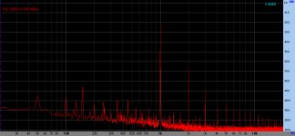
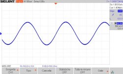
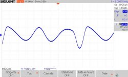
In photo CF the proto. In CFrisp the frequency answer, it is good. I used two loads one at 100Kohm and one at 2700 ohm. In FFt_100k_2700_1_5 vout is the FFT with a load ok 100Kohm (red) and with a load of 2700 ohm (blue) The results is good the II nd is lower but the III is coming up. In the second FFT we have 15 vout on 100 kohm with a good results but with 2700 ohm we lower at 13,44 volt and the shape is bad. Lot of harmonics are up, blu line. The other two image are the residual of THD. The 15 vout is on the load of 100Kohm and it is mainly second. The 13vout is with the 2700 ohm conncted and it is very different!!! In this case the current that flow in a 2700 ohm is 5 mA additional. Of course with a greater swing we will get more THD.
The voltage supply stay always at 323 volt in every case.
If we run with SRPP the results can be in line with these ones.
Maybe we can set at the best the circuit but in this test configuration the performances are quite fine. This to explain what will happens is there are an additional current that flow in the CF; this will happen due a peak signal voltage that can give the grid of the 300B in positive zone.
I will back with IT trafo.
Walter
First of all today I have quickly prepared a CF circuit with a 6SN7 soviet; first stage at gain, Vdc at 320 vdc, R anode 22 kohm (v is at 154), cathode 470 ohm, Ia 7,6 mA with 3,59 volt; second stage a direct connection with a cathode resistor of 15 kohm, Ia af 10 mA the voltage is 159 vdc. The gain is 15. The distortion with 100 mV in and 1,5 vout is around 0,1%, Zout is around 300 ohm With 1 Vin and Vout of 15 vrms we have 0,80% THD.
In photo CF the proto. In CFrisp the frequency answer, it is good. I used two loads one at 100Kohm and one at 2700 ohm. In FFt_100k_2700_1_5 vout is the FFT with a load ok 100Kohm (red) and with a load of 2700 ohm (blue) The results is good the II nd is lower but the III is coming up. In the second FFT we have 15 vout on 100 kohm with a good results but with 2700 ohm we lower at 13,44 volt and the shape is bad. Lot of harmonics are up, blu line. The other two image are the residual of THD. The 15 vout is on the load of 100Kohm and it is mainly second. The 13vout is with the 2700 ohm conncted and it is very different!!! In this case the current that flow in a 2700 ohm is 5 mA additional. Of course with a greater swing we will get more THD.
The voltage supply stay always at 323 volt in every case.
If we run with SRPP the results can be in line with these ones.
Maybe we can set at the best the circuit but in this test configuration the performances are quite fine. This to explain what will happens is there are an additional current that flow in the CF; this will happen due a peak signal voltage that can give the grid of the 300B in positive zone.
I will back with IT trafo.
Walter
Attachments
The proposed cathode follower is AC coupled to the voltage gain stage and DC coupled to the 300B. 160Vdc plate voltage too is low for driving the 300B. It should be at least 50-60V more. Better if 250V. Otherwise you have no headroom to drive the 300B.
Regarding the measurements the distortion you measure is the common cathode + cathode follower. It is not the cathode follower distortion. The load provided by the presence of the grid current is not a low resistive load. Moving towards the cut off it is basically equal to the cathode resistor. So if you have 15K that would the load. On the other side is variable but I don't think it will be as low as 2.7K. Going back to the original example where the 300B works at 420V/75mA, bias around 87-88V, the class A2 operation goes up to 95V peak swing. That will require 5 mA peak into grid in the WORST case which corresponds to less than 0.5W peak that the CF needs to provide the 300B. So the dynamic load (which is in parallel with the cathode resistor) is way more than 2.7K and only one side where the driver tube is linear.
Regarding the Russian 6H8C, I have never had good luck with this tube. Visibly less linear respect to most NOS american 6SN7's and lower mutual conductance. This is one tube that needs careful selection because the average quality in not as good as other Russian tubes. I would say that actually it is quite poor. You need to throw 5 of them in the bin to get a good one....
Your example is misleading. Build the real amp and will see the one with less distortion of all kinds. Then we can discuss. Same thing for the transformer. If you have a transformer that is not up to the task then you are not comparing apples to apples.
P.S.
As you insist with the Audio Note kit, if you really want to compare to the cathode follower driving a power tube like the 300B or 2A3 then build it like the Audio Note Neiro. Just need to use the 6SN7 instead of the 5687 and use one 2A3 or one 300B instead of a parallel single-ended.
As I wrote this circuit, that is correct, can be tuned better , no problem. But nothing will change.
No, the distortion is about the CF.
I don't know if, in this case, the positive zone of 300B can be around a 2K7 but this is not important; the main reason is to show when happen in a CF when, under great swing the load goes down, capacitor or not.
In this case I have 5 mA rms more but the swing is not so high, if I have more swing the THD will be greater, no doubt on this.
Regardin 6SN7 I will use another one, no problem
My example is clear for me; in every case anyone can provide the same test set and the results, no problem for me.
Regarding IT, I have a friend that sell Lundhal, I will order a pair you mentioned then I will prepare a test set.
Regrading AN Kit 1, I insist to say that it is one of the best (and simply) circuit for 300B SE
The variable is the OT, as usual.
Ciao
Walter
I can't see that. If you say so I might believe it but your circuit is not good for driving the 300B in A2. I told you in the beginning that I had doubts about your opinion on CF now I am sure.As I wrote this circuit, that is correct, can be tuned better , no problem.
But nothing will change.
No, the distortion is about the CF.
It is important. Your circuit is not linear enough to drive that low load. Moreover it is not the load presented by the 300B when driving only FEW volts into positive grid. It's like eating an apple and then saying that carrots are not good. It has nothing to with the capacitor.I don't know if, in this case, the positive zone of 300B can be around a 2K7 but this is not important; the main reason is to show when happen in a CF when, under great swing the load goes down, capacitor or not.
The capacitor problem is that it introduces blocking distortion. Also there bias shift because the grid current can only go through the grid resistor. These two things don't happen with DC coupled CF.
Again! I have tried to tell this in very simple words but you don't seem to understand the difference.In this case I have 5 mA rms more but the swing is not so high, if I have more swing the THD will be greater, no doubt on this.
There is no symmetrical current swing. No doubt about this. You can only use your conclusion if you stay in class A1 with no grid current. But not with circuit as is of course because it should have that distortion at full swing, when the 300B is stating to clip, to be good enough.
OK. I might have some breadboarded thing which I used to test 2A3s. I can bring that with a good 6SN7 and then you will see the difference. I am coming next weekend to Italy.My example is clear for me; in every case anyone can provide the same test set and the results, no problem for me.
I insist that their final product called Neiro is better than the kit and not just because of the output transformers. Nowadays the Kondo Audionote Japan is independent again from Audionote UK and it is called Souga SOUGA | AUDIO NOTE.Regrading AN Kit 1, I insist to say that it is one of the best (and simply) circuit for 300B SE. The variable is the OT, as usual.
Why should they use better components with poorer circuit for one of their most important amplifiers?
Last edited:
The most important evidence is that CF change the load line dinamically with the load when it goes down, that's all. And it is possible to see what happen.
We can discuss for hours but I sent the test with this evidence. When you are in Italy we can speak together at my lab.
If I have time in next days I will tune for a better perf. jut to complete the test.
Regarding AN, again, the Kit 1 is very fine; I teste many of them always with a great performance also as listening
Ciao
Walter
ps= two italians that speak in english inside in an american forum is the maximum!!!!
- Status
- This old topic is closed. If you want to reopen this topic, contact a moderator using the "Report Post" button.
- Home
- Amplifiers
- Tubes / Valves
- whats wrong with this 300b SE schematic?