Here we go with our luddite documentation again.
Your luddite documentation is great! Thanks.
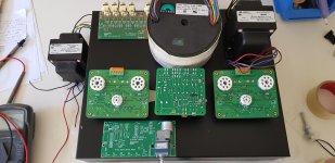
Power Supply Board finished.
Starting on the 2 Amp boards. Just went through entire thread to confirm that for the MKII boards the valve sockets go on the back of the board - see gabo's pics at post #653.
There was also a post by Marc saying that (for the MKII boards) he had reversed the tube pin numbers to accommodate mounting the tube sockets on the back.
This is a better arrangement than the older "MK1" boards.
Cheers,
Ian
My boards haven't arrived yet, but I appreciate the effort you've put in to sort things out. Much appreciated.
I am putting together the parts for building the PSU board and the MKII boards.
Can anybody confirm the correct value of choke to be used with the PSU? I've tried searching through the threads but not come up with anything.
Also is there a layout diagram for these boards? Just makes marking out the chassis easier.
Thanks
Karl
Can anybody confirm the correct value of choke to be used with the PSU? I've tried searching through the threads but not come up with anything.
Also is there a layout diagram for these boards? Just makes marking out the chassis easier.
Thanks
Karl
I am putting together the parts for building the PSU board and the MKII boards.
Can anybody confirm the correct value of choke to be used with the PSU? I've tried searching through the threads but not come up with anything.
Also is there a layout diagram for these boards? Just makes marking out the chassis easier.
Thanks
Karl
Here's the choke.
158T Hammond Manufacturing | Mouser
Also, here's a mouser project for the PSU which also contains the choke. Be aware that this list is not 100% accurate, so go through it and make sure everything is like you want it. But it's easier than starting from scratch.
Mouser Electronics
gabo
I am very pleased to see that the EL34 Baby Huey has still a lot of fans...
I didn't participate to the forum since many months, it is not because I am not interested to answer in the very good discussion, but because I had a very serious health problem and I had a chemotherapy treatment which was really difficult to support therefor I was too tired to make amplifier project and to work in my lab. However after 5 months of treatment I feel a little better and I am more active, I have some hope to be able to participate again to the forum soon.
I see that there was some interest for an MK3 version, but I don't think that a new version will bring a real improvement to the Baby Huey since the actual version (and even the first one) give such a good music sound.
An other more interesting evolution will be a quad KT120 version based on a combination of the Baby Huey and the TENA schematics, I have started the project but it is on hold since I have these health problems, may be if I feel better and if Prasi and Gingertube are interested to help we can finalise this ultimate version ?
The power supply for the MK2 version was also based on the TENA power supply and I apologies for the error on the MOSFET I probably made a mistake with the Eagle library, thanks Ian to have found that...
I will try to be more active soon !
Cheers,
Marc
Great to hear from you Marc!! We've all been thinking about you and glad you are getting better! Keep hanging in there!
gabo
gabo
Baby Huey Tena-ish combo
In reply to Mac's comment on a Baby Huey-Tena combination I did something similar. If there is interest I'll start another thread.
I really have no business trying to design an amplifier but I learn best by doing so I basically did a cut and paste of the tena and baby huey circuits along with a drawing from Audioamp.eu auto bias boards and came up with the PPP EL34 schematic below. i ordered a few boards and finally have time to do some testing this week.
I have a couple extra boards if some is interested in trouble shooting. I'm sure I will need the help.
Take Care,
Evan
Attachments
A new thread was started for the discussion and development of the BH topology with parallel high-power tubes.
See: Baby Huey enters into puberty: 6550 KT88 possibly GU50?
Welcome back, Marc. Very good to hear you are doing better. Hopefully you will run at full power shortly.
Francois
See: Baby Huey enters into puberty: 6550 KT88 possibly GU50?
Welcome back, Marc. Very good to hear you are doing better. Hopefully you will run at full power shortly.
Francois
Here's the choke.
158T Hammond Manufacturing | Mouser
Also, here's a mouser project for the PSU which also contains the choke. Be aware that this list is not 100% accurate, so go through it and make sure everything is like you want it. But it's easier than starting from scratch.
Mouser Electronics
gabo
Thanks Gabo! Much appreciated.
Cheers
Karl
Welcome back Marc,
good to hear that you are feeling better and hopefully will start your diy engine very soon.
In your absence Ian, Francois , Gabo and others have helped to carry the BHEL engine forward...
regards
prasi
good to hear that you are feeling better and hopefully will start your diy engine very soon.
In your absence Ian, Francois , Gabo and others have helped to carry the BHEL engine forward...
regards
prasi
Tubes on back
Ian: I also mounted R42, R43, and R5 on the back and drilled holes in the chassis to expose them.
Then I used one of the meters that Marc recommended, YB5135D LCD Digital Voltmeter DC 200mV/2V/20V/200V/500V DC Voltage Meter Volt Panel Meter Voltage Monitor Volt Meter Voltmetre|Voltage Meters| | - AliExpress
And a panel mount switch to switch between test points so I can adjust the bias from the top of the unit. Works very nice, great suggestion by Marc. Makes it easy to change tubes and rebias. Been thinking about trying some KT120s for parties, but a bit afraid of the load and heat it would generate. I'm also building a 2nd amp and will probably go KT77s.
I did not expose test points for R5, a bit too much voltage there. So just connect a probe and adjust from the top.
Also, are you using one of the buck converters from ebay for the heaters? That PSU board was designed for that. That is very nice as well. I bought one of these, DC-DC Converter 10/12/15/20A 150/250/300/400/1200W Step up Step down Buck Boost | eBay
gabo
Power Supply Board finished.
Starting on the 2 Amp boards. Just went through entire thread to confirm that for the MKII boards the valve sockets go on the back of the board - see gabo's pics at post #653.
There was also a post by Marc saying that (for the MKII boards) he had reversed the tube pin numbers to accommodate mounting the tube sockets on the back.
This is a better arrangement than the older "MK1" boards.
Cheers,
Ian
Ian: I also mounted R42, R43, and R5 on the back and drilled holes in the chassis to expose them.
Then I used one of the meters that Marc recommended, YB5135D LCD Digital Voltmeter DC 200mV/2V/20V/200V/500V DC Voltage Meter Volt Panel Meter Voltage Monitor Volt Meter Voltmetre|Voltage Meters| | - AliExpress
And a panel mount switch to switch between test points so I can adjust the bias from the top of the unit. Works very nice, great suggestion by Marc. Makes it easy to change tubes and rebias. Been thinking about trying some KT120s for parties, but a bit afraid of the load and heat it would generate. I'm also building a 2nd amp and will probably go KT77s.
I did not expose test points for R5, a bit too much voltage there. So just connect a probe and adjust from the top.
Also, are you using one of the buck converters from ebay for the heaters? That PSU board was designed for that. That is very nice as well. I bought one of these, DC-DC Converter 10/12/15/20A 150/250/300/400/1200W Step up Step down Buck Boost | eBay
gabo
OK Amp Boards are loaded, first let me say welcome back Marc, hope you are recovering well.
Advantage of knowing the circuit intimately is that whilst loading I can check every component against the schematic and do an on the spot review as I build.
There will now be a reasonable delay as I tackle the metal work.
There were some mods suggested thru' this long thread BUT for your info here is what I did while loading boards (what I considered useful out of all the suggested mods).
1) R7 and R8 were changed, value the same (220K) but used 2W metal films for increased voltage rating (I actually used 240K 2W because that's what was in parts bin)
2) R14 and R15 changed from 270R 2W to 1K 2W, past experience showed that EL34 in Ultralinear need 1K (I had oscillation grief on a previous amp with 150R). Would have liked to use 1K 5W but wouldn't fit.
3) R33 and R38 changed to from 390R to 270R This increases the source follower current from 1.7mA to 2.4mA. May give improved high frequency response and stereo imaging. I would have liked to use 220R for 3.0 mA but that would push dissipation in Q7 and Q9 a bit too high. For MK3 designers change Q7 and Q9 to an MJE340 or similar, or ditch the "Ring of 2" current source entirely and use a high voltage current source device.
4) R39 used was 33K as per schematic while board component overlay says 15K. That's just to accommodate higher -ve supply.
5)Changed R16 to 47K, Want to keep LED1 current to about 2mA, with higher -ve rail the original 15K was a bit low
Note also that in the Mouser supplied parts C6 and C7 are 120uF/500V. The increased voltage rating is good (I will have around +440 to +450V on my B+ rail).
I didn't change R3 and R4 but if I had thought about them before loading I would have used 4K7 for just a bit more ECC83 parasitic oscillation proofing.
Oh and I used some "Audio Jewellery" 0.1uF 1000V Polyproylene for the C1 and C2 coupling caps but what was provided from Mouser were pretty good.
Cheers,
Ian
Last edited:
Ian: Did you also change R13? That was previously discussed as possibly changing from 39K to something like 16-20K.
Also, would be interested in what the high voltage current source device, to replace the "ring of 2," might look like?
gabo
Also, would be interested in what the high voltage current source device, to replace the "ring of 2," might look like?
gabo
gabo,
I have done a temporary fudge for R13 at this time. 2 off 6K8 resistors stuck up in air so that I can put another resistor between them. That will allow me to tune R13 from 13K6 upward.
For the high voltage current source you use a DEPLETION Mode Mosfet, plenty to choose from but here is one example:
https://au.mouser.com/datasheet/2/240/Littelfuse_Discrete_MOSFETs_N-Channel_Depletion_Mo-1623348.pdf
You put the current set resistor in the Source and tie the gate (via a gate stop resistor) to the side of that source resistor away from the source. Just like cathode biasing a tube.
Commencing the "Metal Bashing" today.
Cheers,
Ian
Just contemplating adding remote control 4 input channel source selection and volume control BEFORE I start making holes.
I have the boards for that. Or just might use a flash stepped shunt attenuator I have with single input, decisions, decisions.
Note I have cleaned the flux from the power supply and amp boards using isopropyl alcohol and a tooth brush.
ASIDE: Had Isopropyl alcohol left over from making my hand sanitiser using tea tree oil, eucalyptus oil, the alcohol and distilled water (all the shops have run out).
Cheers,
Ian
PS One thing missing from the Mouser Power Supply kit is the clips to hold the IRF9610 and the LM317T to their heatsinks.
Attachments
Last edited:
Chassis Layout
Nice to have channel switching and volume, I'm using mine with a preamp so just went with inputs.
Where I live there are a number of local/small distilleries, they have all changed over production to produce an alcohol based hand sanitizer.
I need to go back to Mouser and see if I can find a better option for the heat sinks. You mentioned before that they blocked access to the diode that's just in front of the 9610 as well.
I actually used these that I found on ebay. They fit the outline on the circuit board to a tee and do not block the diode. They also have a threaded screw hole, so no clips needed, just screw the 9610 and LM317 directly to the sinks. Would be nice if I could find these on Mouser to add to the project.
Amazon.com: Electronics-Salon 4x TO-220 Heatsink, Small Power Aluminum Heat-Sink , SKU: HS-001-4: Industrial & Scientific
gabo
Just contemplating adding remote control 4 input channel source selection and volume control BEFORE I start making holes.
I have the boards for that. Or just might use a flash stepped shunt attenuator I have with single input, decisions, decisions.
Note I have cleaned the flux from the power supply and amp boards using isopropyl alcohol and a tooth brush.
ASIDE: Had Isopropyl alcohol left over from making my hand sanitiser using tea tree oil, eucalyptus oil, the alcohol and distilled water (all the shops have run out).
Cheers,
Ian
PS One thing missing from the Mouser Power Supply kit is the clips to hold the IRF9610 and the LM317T to their heatsinks.
Nice to have channel switching and volume, I'm using mine with a preamp so just went with inputs.
Where I live there are a number of local/small distilleries, they have all changed over production to produce an alcohol based hand sanitizer.
I need to go back to Mouser and see if I can find a better option for the heat sinks. You mentioned before that they blocked access to the diode that's just in front of the 9610 as well.
I actually used these that I found on ebay. They fit the outline on the circuit board to a tee and do not block the diode. They also have a threaded screw hole, so no clips needed, just screw the 9610 and LM317 directly to the sinks. Would be nice if I could find these on Mouser to add to the project.
Amazon.com: Electronics-Salon 4x TO-220 Heatsink, Small Power Aluminum Heat-Sink , SKU: HS-001-4: Industrial & Scientific
gabo
I think I found the right heat sinks on Mouser. I have added these to the PSU project.
HSE-B20254-035H-01 CUI Devices | Mouser
gabo
HSE-B20254-035H-01 CUI Devices | Mouser
gabo
- Home
- Amplifiers
- Tubes / Valves
- EL34 Baby Huey Amplifier