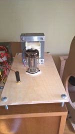
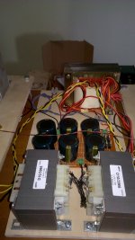
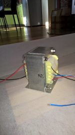
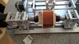
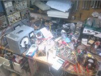
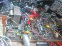
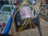
This is my latest creation. It is still prototype. Output transformer is also my build (EI120 x 55mm laminations).
Matej
Matej
Attachments
That is very interesting. The circuit looks like a cascode circuit. Normally, a stand-alone triode wired pentode has a low to medium plate resistance.
But one characteristic of a cascode circuit is that the output device (in this case a tube) has a very high output impedance. That can cause two things: Low damping factor Low frequency response that rolls off early, depending on the output transformer's primary inductance.
But one characteristic of a cascode circuit is that the output device (in this case a tube) has a very high output impedance. That can cause two things: Low damping factor Low frequency response that rolls off early, depending on the output transformer's primary inductance.
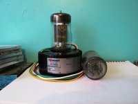
I sat up when I saw your post.Nice simple scheme.The SRS551 encourages this as it is quite sensitive.Looking at the internels of the valve I see two pentodes joined together,but I may be wrong.I have 2 sets of these valves including all I need to complete a build except those unobtainium sockets.So they sit in storage ......I'm so envious of you matejsirk,thanks for posting.
Attachments
Last edited:
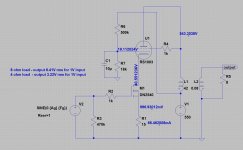
The symbol you've used for the DN2540 is an enhancement mode MOSFET symbol, the depletion-mode symbol has a continuous line for the channel, not a broken line, to indicate the channel conducts by default.
Well, yes.
Sorry.
I just took a screen-capture of the flawed drawing.
Didn't want to invest the time re-drawing it.
But you are absolutely correct.
SOLID line means “conducts-with-VGS ≡ 0”
… which requires VGS < 0 to cause channel pinch off.
BROKEN line means “non-conducting-at-VGS ≡ 0”
… which requires VGS > 0 to cause channel opening!
⋅-=≡ GoatGuy ✓ ≡=-⋅
The symbol you've used for the DN2540 is an enhancement mode MOSFET symbol, the depletion-mode symbol has a continuous line for the channel, not a broken line, to indicate the channel conducts by default.
I think this comment does not make the essence of the subject, it is strongly urged not to lose the thread, there will surely be another thread or post that has to do with signs which are arbitrary and almost everyone knows that this transistor is a Depletion mode.
@GoatGuy:
Thanks for rescuing the circuit, apparently you have made measurements and at least you could simulate it. In that case I would like to know if it is true that the output impedance is so high because it is a cascode integrated by the transistor and the RS1003.
Hi folks,
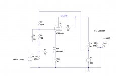
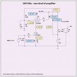
since I got a number of this kind of tube , i´m breadboarded a Circuit about this tube.
Here are the schematic.
Output : up to 21W ,15W with 2,8% THD
Input 2,5V rms for full output
110W input power
The opt is homebrewed on a M102b core with 2mm air gap salvaged from post office equipment , prim. 2500 Ohms
There is lot of room for improvements. The SRS 551 is indulgent animal and forgives mistakes.
The driver tube is an EF80 /EF800. The sockets are difficult to obtain when not in Europe, but I´m sure the chinese got a replica to offer pricely. Porcelain is still their business.
Edit: R5 shall be 470 ohms instead 820 ohms!!
Attachments
Last edited:
- Status
- This old topic is closed. If you want to reopen this topic, contact a moderator using the "Report Post" button.
- Home
- Amplifiers
- Tubes / Valves
- Tube amp of different kind - SRS551