hpeter,
Post # 19 I would like to know how [much] with capacitor, the sound gets worse, for the circuit parameters stated; can we hear the difference?
Since the plate current is not changing much (high impedance CCS; And "assuming not much additional loading"), that means the cathode current is not changing much, and the self bias resistor can take care of almost all of that current change. Yes, the grunge created by the (electrolytic) bypass capacitor may affect the sound, but will do so at a much lower amount versus when the plate is loaded by a moderate impedance, not a high impedance.
hpeter,
Post # 19 I would like to know how [much] with capacitor, the sound gets worse, for the circuit parameters stated; can we hear the difference?
There is an example in my book of bootstrapping a 12AU7 gain stage from a cathode follower (fig. 7.24 / 7.25), where distortion triped from 0.1% to 0.3% (10Vrms) when the cathode capacitor was added to the gain stage.
Do you mean CCS on plate & cathode at the same time, are you serious?
Even Morgan Jones, one of the contemporary tube popes, suggests this, see:
I think he refers to Tube Amplifiers, 3rd edition, where Jones shows a LTP phase inverter with two CCS's as plate loads and one as tail. I've tried to built it - without success. It is plain impossible to adjust three CCS's to get them cooperative. MJ surely was in an error here.There's an example in Valve Amplifiers where there is a two-transistor cascade in the cathode circuit, many million of ohms, and a single transistor CCS in the plate circuit, less than 200K. According to the book, the superior cathode CCS dominates and sets the operating conditions. FWIW!
Best regards!
it was year ago, when i was testing this. maybe i should try again and compare.hpeter,
Post # 19 I would like to know how [much] with capacitor, the sound gets worse, for the circuit parameters stated; can we hear the difference?
Since the plate current is not changing much (high impedance CCS; And "assuming not much additional loading"), that means the cathode current is not changing much, and the self bias resistor can take care of almost all of that current change. Yes, the grunge created by the (electrolytic) bypass capacitor may affect the sound, but will do so at a much lower amount versus when the plate is loaded by a moderate impedance, not a high impedance.
but i remember that i was desoldering rk caps immediately after listen..

why cathode cap might destroy the sound, could be capacitor nonlinearities, for example behaving differently to halfwaves. (charge-discharge cycles)
EXAMPLE ceramic smd hi-value caps dielectrics changes a lot to dcbias/temperature/humidity/ or has piezo properties.
with hioki 4k€ lc bridge i was measuring few smd low-esr, and normal wet caps. (+old wire ended)
i could see that beyond 5khz, µfarad value drops fast, and above 20khz they were more like chokes.
foil caps were rock solid 20hz-200khz. minimal inductance behavior.
i am using now 6sl7 ~180v and 2,2ma; it has just 0,7v on rk.
a high gain gyrator stage, think for a second - if in cathode circuit would be any SMALL nonlinearity component added.
it would be strongly amplified (like in common grid circuit) by this stage.
this is also reason why i not doing led bias.
when i switched from plate r., to gyrator -sound improvement was big.
i came up with this possible explanation.
ecc83 under gyrator had gain ~85 ish ,IIRC. no cathode cap.
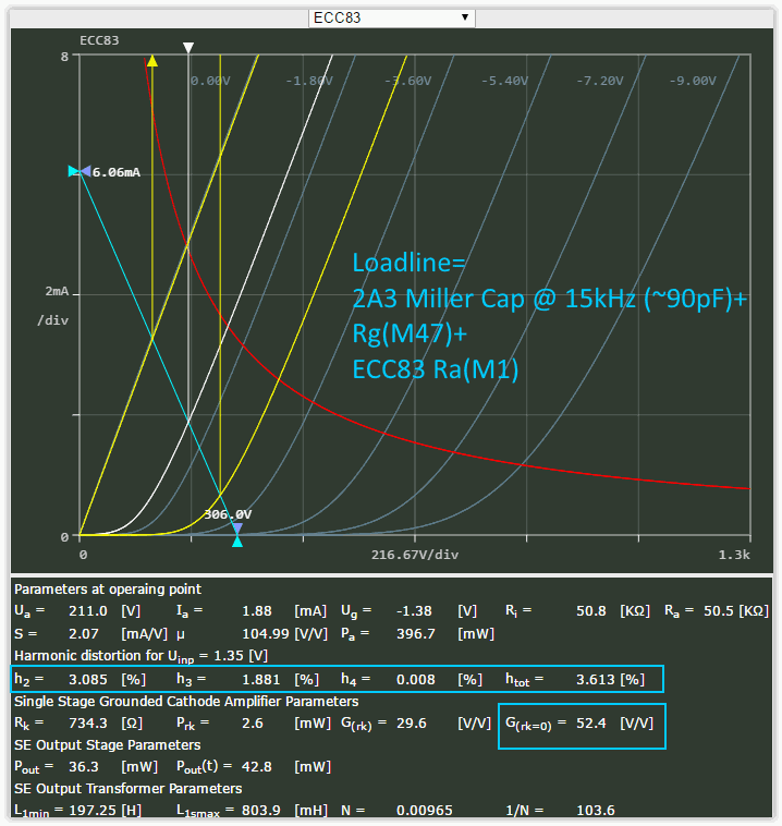
plate resistor sound was not pleasant, and it was more bassy, under blanket. (2a3 millers "shorting" the ecc83 drive at treble # from ~83k loadline -> ~48k)
Another possibility is that the PSRR is degraded enough without the bypass capacitor that HT noise is affecting the sound. That was another thought I had about the very small cathode resistor in the 12au6 experiment on this thread- ra+Rk(mu+1) is not so very different in this case, and maybe the HT is clean enough not to matter much. Although with the CCS tilted to 270k, it could still make quite a difference. What I'm reading here is that the circuit was not initially designed to use the CCS and so can get by OK without one- it's not apparently relying on a vast PSRR to lose HT noise.
That circuit with more than 1 CCS has led me to wonder what in Morgan Jones is straightforwardly achievable and what might have to be cajoled into cooperation by someone far more capable than myself.
That circuit with more than 1 CCS has led me to wonder what in Morgan Jones is straightforwardly achievable and what might have to be cajoled into cooperation by someone far more capable than myself.
Such an impedance is likely to be swamped by the plate resistance, similar to the impedance of an LED being so small in comparison.why cathode cap might destroy the sound, could be capacitor nonlinearities,
On the other hand, some cathode swamping has been known to linearise plate resistance, which, when loading the stage with a CCS, becomes the primary driving impedance of the stage.
I doubt merlinb would miss such an error as this.Another possibility is that the PSRR is degraded enough without the bypass capacitor that HT noise is affecting the sound.
I was actually referring to post #19 "somehow the sound gets worse!" without noting who had posted it. I've personally often run into sonic difference where I strongly preferred one variation to another without being able to account for it in quantifiable terms. What I'm really concerned about is what your biasing was like when you ran into thermal runaway, as you mentioned in reference to the 270k grid leak choice. Maybe I'll poke around this forum for tales of thermal runaway!
tapehead ted,
1. Were you referring to my post # 16 where I talked about a KT66 with cathode self bias, and a 270k grid resistor? No problem when the plate + screen dissipation is less than 27 Watts, the maximum grid resistance is 1 Meg Ohm. And with cathode self bias, for greater than 27 watts plate + screen dissipation, the maximum grid resistance for cathode self bias is 500k Ohms.
Fixed bias KT66 specs are completely different, plate + screen dissipation less than 27 Watts, grid resistor is 220k Ohms maximum; and plate + screen dissipation more than 27 Watts, grid resistor is 100k maximum.
2. The thermal run-away I saw with a Red Plate was many years ago. I learned my lesson Then. An EL34 with fixed adjustable bias was set to 50mA cathode current. The grid resistor was 270k Ohms, all ran OK with that circuit. Then I decided to try other tube types. I substituted a 6550. With 270k Ohms in the grid circuit, I adjusted the cathode current for 50mA. It was not long after the amp was warmed up that I heard terrible distortion, and I looked at the amp and the tube plate was glowing red (I immediately turned the amp off). In looked at the grid resistor specs, I saw my mistake, the maximum specified grid resistor is 50k Ohms.
Some tubes will work if you exceed the maximum grid resistance, some tubes will not. Tubes of the same type, and even of the same manufacturer may not all be the same. If you exceed the specifications, your mileage may vary.
Now you see why I tend to be a little conservative when picking the grid resistor.
3. I was using a 12AU7, not a 12AU6 in my KT66 amp. The amplifier output hum and noise was less than 100 microvolts Both with the 12AU7 cathode bypassed, and without the cathode bypassed.
Last edited:
Such an impedance is likely to be swamped by the plate resistance, similar to the impedance of an LED being so small in comparison.
On the other hand, some cathode swamping has been known to linearise plate resistance, which, when loading the stage with a CCS, becomes the primary driving impedance of the stage.
if i understand correctly, you thinking that nonlinearities in cathode circuit does not affect high-gain stage much .

So people DO still say "your mileage may vary!"Some tubes will work if you exceed the maximum grid resistance, some tubes will not. Tubes of the same type, and even of the same manufacturer may not all be the same. If you exceed the specifications, your mileage may vary.
Now you see why I tend to be a little conservative when picking the grid resistor.
3. I was using a 12AU7, not a 12AU6 in my KT66 amp. The amplifier output hum and noise was less than 100 microvolts Both with the 12AU7 cathode bypassed, and without the cathode bypassed.
Sorry, I knew it was a 12au7, I just have 12au6 on the brain just now. Finally located a few different triode charts for that one.
I haven't seen the red plate (somehow?!) and I haven't had a tube burn out before my eyes that I can recall, but I've seen some circuits that eat tubes and on inspection exceeding the max grid resistance was an obvious culprit. Are all culprits guilty? Anyway I've been eyeing that one with suspicion.
I was thinking a resistor (a carefully selected moderate value), multiplied by gain.if i understand correctly, you thinking that nonlinearities in cathode circuit does not affect high-gain stage much .
- Status
- This old topic is closed. If you want to reopen this topic, contact a moderator using the "Report Post" button.
- Home
- Amplifiers
- Tubes / Valves
- Cathode bypass capacitor related question