Guys,
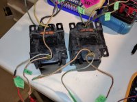
These two opts sitting for dust and wish to make use of them but don't know how to identify if they are SE and or PP. There are four wire at one side and three on the other side. The side with four wire where I could found the black and presume they are the secondary. I measures with the black as reference and I got 0.5/0.6/0.7 respectively and both opts are the same.
The others side with three wire which I took the wire with red dot as reference, I got 187.6 /180.3 ohm and other one with 173.7/185.3 ohm.
Please don't hesitate to give ideas and advices.
Thanks in advance
Albert
Attachments
No idea who made them, but I'd hazard a guess they are PP transformers for pentodes like 6L6 or similar. You can measure the ratio quite easily and figure out the primary impedance.
The secondary winding with the highest resistance (in this case) should be 16 ohm... Using a variac and a filament transformer drive the 16 ohm secondary with something like 1Vrms and measure across the entire primary (caution moderately high voltage will be present) - say you measure 20Vrms this implies a n1:n2 ratio of 20:1 (where n1 is the primary), square this and multiply by 16 ohms. In this example it would give you 400 x 16 or 6400 ohms plate to plate.
The secondary winding with the highest resistance (in this case) should be 16 ohm... Using a variac and a filament transformer drive the 16 ohm secondary with something like 1Vrms and measure across the entire primary (caution moderately high voltage will be present) - say you measure 20Vrms this implies a n1:n2 ratio of 20:1 (where n1 is the primary), square this and multiply by 16 ohms. In this example it would give you 400 x 16 or 6400 ohms plate to plate.
These are clearly Push Pull transformers. You can see the lines on both sides that indicate Interleaved E and I laminations. A single ended transformer would have the all the E's on one side, and all the I's on the other side, with a single line separating the E's from the I's.
Do not use a battery to test the transformer.
If you have a 6.3V filament transformer, you can power the 120V primary, and then connect the 6.3V to the black and 16 Ohm tap. Careful, without the variac, there will be very high voltage from primary center tap to the other primary leads. Do Not let any leads short to any other leads. Measure the ratio of 6.3V to the secondary, versus center tap to each 1/2 primary lead, one at a time. See my calculation below for the 1/2 primary impedance and the full plate to plate primary impedance.
If you do not have a 6.3V filament transformer, then . . Do you have an amplifier. play it very quietly on a test tone; If you do not have a test tone, use the constant Hiss from an FM tuner that is tuned between stations (and with the mute not turned on). Then connect the amp output to the 16 Ohm tap and the black common lead (secondary leads). Carefully measure the primary from the center tap to the outside primary leads (one outside primary at a time). Those 2 voltages should from the center tap should be about the same.
You then have to measure the voltage on the secondary (16 to black). Now you calculate the ratio. (V 1/2 primary) / (V secondary). ((Ratio)squared) x 16 = impedance of 1/2 secondary. Multiply by 4 to get the plate to plate impedance. If you question why this way, I will further explain (it has already been fairly well explained by others in this thread.
I measured with 5v ptx at 16 ohm ( 0.7ohm to black ). On the primary I took line with red dot as center. I got 63/63 on both opts. The ratio is almost 13:1. If I go with Kevin's formula, it is a 2.7k pp opt. Am I on the right track?
I want to try 6a3Summer's formula but not sure the numbers I got is correct.
Please kindly advise
Albert
I want to try 6a3Summer's formula but not sure the numbers I got is correct.
Please kindly advise
Albert
I measured with 5v ptx at 16 ohm ( 0.7ohm to black ). On the primary I took line with red dot as center. I got 63/63 on both opts. The ratio is almost 13:1. If I go with Kevin's formula, it is a 2.7k pp opt. Am I on the right track?
I want to try 6a3Summer's formula but not sure the numbers I got is correct.
Please kindly advise
Albert
If that is 63-0-63 or 126V end to end I get about 10K P-P [((126/5)^2)*16].
If that is 63-0-63 or 126V end to end I get about 10K P-P [((126/5)^2)*16].
Yes, it's 63-0-63.
In this case I have a pair of 10k opt. What are they good for? Is 10k too big for 807pp?
Last edited:
Using my equation plate to plate: 126/5 for n1:n2 of 25.2
squaring that = 635, and multiplying that by the secondary impedance of 16 ohms = 10,160 ohms plate to plate.
Or P-P = ((126/5)^2)*16
That's surprisingly high but might be suitable for KT66/6L6/807 at relatively high plate voltages in pentode connection.
squaring that = 635, and multiplying that by the secondary impedance of 16 ohms = 10,160 ohms plate to plate.
Or P-P = ((126/5)^2)*16
That's surprisingly high but might be suitable for KT66/6L6/807 at relatively high plate voltages in pentode connection.
")
Are these big and heavy? If so, maybe they're meant for over 40W output. They don't look very big to me in the picture. If they are indeed smaller/lighter, then they'd be of the 20W class meant for PP EL84 or PP 6V6 (4 or 5W triode, 10 to 20W pentode).
If they're the big/heavy type, 10k:VC is also good for PP 6L6 or PP EL34 in triode, if you're okay with a 10 to 15W watt amplifier running on a 400V plate supply.
According to Wavebourn, a big 10k PP OPT is just what you want for a pair of GU-50 in pentode. I think the usual recipe is about 600V on the plates and 200V on the screens. That would make a lot more power. But only if these are big OPTs meant for 50W output.
--
Last edited:
Of course no loudspeaker really equals its rated impedance all across the 20Hz to 20kHz frequency band.
But put the loudspeaker on its respective tap.
Otherwise . . .
1. You will get 2 times the insertion loss through the transformer, due to the DCR of the primary, and the DCR of the secondary. If the insertion loss was 1 dB with the loudspeaker on its respective tap, now the insertion loss will 2 dB.
2. You only get 1/2 of the damping factor by doing it that way too. If the damping factor was 5 with the loudspeaker on its respective tap, now it is only 2.5.
Just understand those two factors before deciding how to use the transformer.
Last edited:
Triode wired Pentodes and Triode wired Beam power tubes will not give as much output power as the same tubes wired in Pentode mode and Beam Power mode.
So why use Triode wiring?
1. Simple
2. No Negative Feedback required; not having it there means it does not need to be adjusted or compensated, no oscillations, good square wave shape, etc.
3. Low distortion without Negative Feedback.
4. Reasonable damping factor without Negative Feedback on your 10k Ohm output transformer.
In triode wired mode, you can use plate voltages up to the screen voltage rating:
Triode wired 807 tubes can take up to 400V on the screens (only 300V in Beam Power mode).
6L6GC 450V (not 6L6, 6L6G, 6L6GB)
EL34 450V
KT77 800V (please do not use that much voltage)
7591 440V (and has the lowest filament currents of all these tubes)
KT66 550V (please do not use that much voltage)
KT88 600V (please do not use that much voltage)
Wow! You have lots of options here, any of these should sound great up to the power out.
It also depends on the circuits before the output tubes.
You will have to measure the voltage across the 100 Ohm resistor that goes from the screen to the plate. Calculate screen current (Vp - Vs)/100 Ohms = Is
You will have to measure the voltage from the plate to the cathode, Vp
You will have to measure the voltage from the screen to the cathode, Vs.
Calculate the screen dissipation, Vs x Is = screen Watts.
make sure screen Watts is within the tube rating, if it is to high, you have to either use more negative control grid fixed bias, higher resistance cathode self bias resistor; or lower the plate voltage (by lowering the voltage to the center tap of your output transformers).
You can make the circuit simple by using individual cathode self bias resistors that have individual bypass capacitors.
Have fun, whatever topology you decide on.
If you can build a negative power supply, you can use a current source and cathode coupled phase splitter to drive the output tubes.
That is pretty simple, and can be low distortion.
Just a thought.
We all have our favorite way to do things.
I am working on a circuit with the 6.3 filament secondary for the negative supply. no extra secondary required.
I have a couple of kinds of simple current sources that can use that negative supply.
- Status
- This old topic is closed. If you want to reopen this topic, contact a moderator using the "Report Post" button.
- Home
- Amplifiers
- Tubes / Valves
- Help identify these opt.