Hi soulmerchant,
It is hard to beat the German post small-signal tube as an input/driver (C3g, C3m, D3a .... etc).
What is the input voltage in your DC C3g-2A3 amp for maximum output power?
About 1Vrms, or so ??
Maybe C3m would be more applicable, imho.
For me, in amplifier good input/driver stage is more important than Oriented HiB, Amorphous or M3 grain oriented core in OPT.
I use pro audio input levels, so input for maximum output power is about 1.22v rms. But to be honest, even standard consumer input works well on my setup. I'm using 2-way speakers (external crossover) with 94dB sensitivity.
C3m is very nice if you can manage the 20v heater requirement.
Very clever but what about the D3A
Any comments on that tube
D3a is getting too expensive imho, but that is probably due to people using it for phono or maybe headphone amp duty.
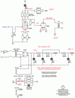
Here is the struggle you will get into with direct coupling most of these little triode strapped pentodes:
You get the idea that direct coupling will save all your 'troubles'. No more 'boutique expensive audiophool coupling caps'. No more heavy expensive interstage transformers that (due to your inadequate calculations) roll off your frequencies. But hey.. its just not that simple.
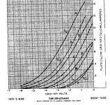
For D3a, take a HARD look at the specs sheet. Really hard... Those german engineers created very detailed specs sheets for these impressive little valves...
You see that your triode strapped D3a has nice low internal resistance when triode strapped, but be careful! That's biased for 24mA and 160V on the plate! For direct coupling, 160V is too high.... so you will want a lower plate voltage... and don't forget, you must still bias it to get decent headroom.
At first you imagine that a plate voltage of 130V will be OK. So you look at the triode curves and you really don't want to bias into the knees of the curves, right? You think, hmm.... maybe -1.25V bias will be ok. Yes, If you are willing to accept an input coupling capacitor, then you can do a nice some grid bias (and solve a LOT of headache at this point) but if you are some kind of audio direct-coupling purist and don't like that idea so are mostly stuck with a cathode resistor, etc.
Now look at the D3a specs sheet for these values and you will see you need 17mA through your CCS. You look at your internal resistance for 17mA and you see that its about 2.5Kohm. Sounds OK so far?
However when you set it up on your breadboard.. and discover... hmmmm sound is NOT so High-End. Kind of 'Tubey' sound. You realize that bias at -1.25V really isn't enough. Its just too little headroom even for consumer audio transient responses. You can see this on your scope too.
So then you take your D3a and want to bias at -1.5V you will suddenly need to push the current way down....to say 8mA. The specs sheets don't lie and the original manufacturer measurements were very good. The internal resistance at 8mA is about 3.8Kohm and on a steep incline if your current for any reason would drops lower. You discover that bias at -1.5V still didn't provide enough headroom even for consumer audio... The sound is just not there... kinda bla....with such low current on this valve either... ugh..
At this stage you might also think.. ok then maybe I can accept a higher plate voltage, but then your direct coupling requires bigger cathode resistor on your 2a3 or 300b, etc. Maybe the input coupling cap is worth testing out (*hint*hint*).
Just my feedback.
Ian
Last edited:
For me, in amplifier good input/driver stage is more important than Oriented HiB, Amorphous or M3 grain oriented core in OPT.
Absolutely agree.
Thanks for info.
20V heating for C3m is not problem. 2x6,3Vac windings in series then voltage doubler.
I think C3m is "born" for DC 2A3 amp.
You didn't find the huge plate resistance to be detrimental? In triode the gain is simply too low, but I hear that triode with an IT is a nice combination.
No. C3m plate resistance will be about the same as for C3g (about 2.5-2.6 kΩ in triode mode). See triode curves for both tubes.
No. With CCS (or gyrator in your case) in C3m anode, and with about 1.7Vrms at the input, you get full power from DC 2A3 amplifier.
To drive 2A3 (about 85Vpp) each tube with μ ~~ 20 is quite sufficient.
No. With CCS (or gyrator in your case) in C3m anode, and with about 1.7Vrms at the input, you get full power from DC 2A3 amplifier.
To drive 2A3 (about 85Vpp) each tube with μ ~~ 20 is quite sufficient.
Last edited:
D3a is getting too expensive imho, but that is probably due to people using it for phono or maybe headphone amp duty.<snip>
For one with D3a on the bench at the moment it does come down to bandwidth when triode strapped. I run the tube at a couple hundred mV of bias, fixed 10mA Ip, and drive signal is ~150 mV p-p. CCS load.
With mu 75, even 40 ohms Rk adds >3k to the 2k Rp for 5k3 (you are suggesting even higher?), and it does roll-off around 15-18kHz on the scope. Reduce Rk to 10R and increase Ip to 15mA?
Hanze.
Last edited:
For one with D3a on the bench at the moment it does come down to bandwidth when triode strapped. I run the tube at a couple hundred mV of bias, fixed 10mA Ip, and drive signal is ~150 mV p-p. CCS load.
With mu 75, even 40 ohms Rk adds >3k to the 2k Rp for 5k3 (you are suggesting even higher?), and it does roll-off around 15-18kHz on the scope. Reduce Rk to 10R and increase Ip to 15mA?
Hanze.
Hi Hanze
If you are looking at the output impendance, it depends whether or not you bypass the cathode resistor.
if you are bypassing the cathode or using LED, or negative grid bias, etc then you can pretty much assume:
Output impedance = ra || Rp
So if you properly by-pass the cathode, then you don't really need to take it into account for the output impedance calculation...
However if you do not bypass the cathode, then:
Output impedance = ra' || Rp
where ra'(unbypassed Rk) = ra + (mu + 1)*Rk
Still, for unbypassed cathode adding (mu+1)*Rk is not always sooo bad - don't forget that it is in parallel with the load. I kind of like the un by-passed stage for a variety of reasons. Yes, there is negative feedback and less gain and higher ra though. Those things are obvious.
Also, if you are using a CCS or gyrator, and DC connect right off the plate, Rp is a huge effective value. Of course it can vary over frequency depending on the CCS devices and implementation. Life gets complicated again... But let's not let that distraction get in our way today either.
")
So, if I understand what you are doing above correctly, the drive signal is 150mV AC RMS? A tiny signal for sure. Mic or phono perhaps?
For what you have above I would consider even trying 20mA and an Rk of 20 ohms if the plate volts is not an issue for your application. Or maybe 15mA and 25 ohms... If the cathode is bypassed I would just go for a higher bias value.
Last edited:
http://www.bartola.co.uk/valves/tag/d3a/ test data on said tubes
I think I will stick to 6SF5 as the current draw is very low and performance very good
May try WE409A/ 6AS6 strapped in Triode is under 4mA plate load and a Mu of 35 or so in Triode
真空管(Electron tube) 規格表データベース | 「6AS6」の検索結果
I think I will stick to 6SF5 as the current draw is very low and performance very good
May try WE409A/ 6AS6 strapped in Triode is under 4mA plate load and a Mu of 35 or so in Triode
真空管(Electron tube) 規格表データベース | 「6AS6」の検索結果
Attachments
6SF5 has a huge mu, but also huge internal resistance. Such a high output impedance won't do a good job driving your 2a3. Basically its like half a 12ax7 in an octal socket.
Maybe this sounds good to you, but I have a pretty good idea of what it sounds though. It can be a LOT better.
You could stick a mosfet follower after it to get some low impedance drive on your 2a3 grid. A good contender is ZVN0545A.
Maybe this sounds good to you, but I have a pretty good idea of what it sounds though. It can be a LOT better.
You could stick a mosfet follower after it to get some low impedance drive on your 2a3 grid. A good contender is ZVN0545A.
Last edited:
Member
Joined 2009
Paid Member
This has been a key question for me too... why do wimpy drivers for 2A3 work as well as they do?
6SF5 has a huge mu, but also huge internal resistance. Such a high output impedance won't do a good job driving your 2a3. Basically its like half a 12ax7 in an octal socket.
Maybe this sounds good to you, but I have a pretty good idea of what it sounds though. It can be a LOT better.
You could stick a mosfet follower after it to get some low impedance drive on your 2a3 grid. A good contender is ZVN0545A.
Indeed with a Source Follower can do 40dB and 50kHz bandwidth. Distortion around 0.35% at 150vpp, not too shabby, of course there are more linear valves but it can do the job well here.
http://www.bartola.co.uk/valves/2017/06/04/6sf5-driver-for-300bgm70813-se-amps/#more-6465
I haven’t tested how it sounds as it was a bench test, so can’t make final judgement.
Most likely I doubt anyone needing a 40dB gain with the higher output levels of sources today
Probably best suited for RIAA as microphonic is low
Cheers
Ale
I tend to run the 6SF5 upto .8mA and the 6A3 ( constant current source DC) at 50mA allows me to use the less expensive ISO FC12S at 3 - 3.5 watts
This combination works exceptional performance
I use a Tektronix TM515 and bandwidth easily reaches 40kHz at -1.5dB with 1 watt load
I have used many different front end tubes over the years
6SL7 6SN7 WE417A 6688 ( in triode mode )5687 STC5A/170K ( triode mode ) and still prefer the 6SF5 with no capacitors
A Copper Teflon Vcap at $170 each buys me an ISO FC12S or NP Acoustic output transformer so DC couplings a no brainer ,great sound 6SF5 is $5 6C4C $30 means more money to buy Berrillium compression drivers
Member
Joined 2009
Paid Member
loftin white+shishido 2a3 use 12AX7 with plates strapped togeater
Not a big fan of this configuration the two plates never completely match
The 6SF5 has a single quite large curved plate . The curved plates do tend to sound great no matter what tube used them including 6SN7 and 6SL7 variants but the 6SF5 is fast and clean and in the circuit I have designed very good bass response for a Wimpy driver
Member
Joined 2009
Paid Member
All I can say is this. Once I got a really good low impedance source driving the 2a3 grid, I thought wow... this is really starting to sound like music. Waaaay less listening fatigue. Even recordings that I thought were mediocre suddenly sounded VERY good.
but I guess everyone has their own journey.
but I guess everyone has their own journey.
- Status
- This old topic is closed. If you want to reopen this topic, contact a moderator using the "Report Post" button.
- Home
- Amplifiers
- Tubes / Valves
- Single Ended 2A3/6A3/6B4G DC coupled & Transformer choices