Aikido All-in-One PCB with Tube Rectifier
All-in-One Aikido & Vertical vs Horizontal
Tube Rectifier heater voltage
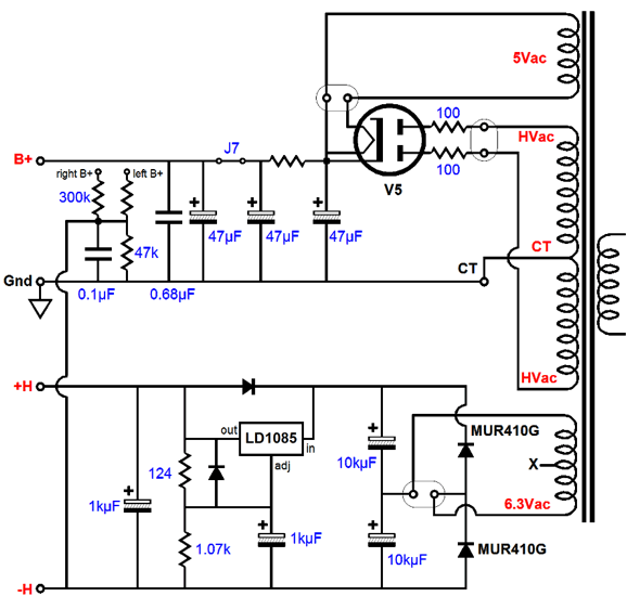
If I'm not mistaken the 5Vac is connected not only to the heater but the B+ supply as well. Does this mean that using that using rectifiers 6.3Vac @ various amperage's from 1.2A all the way up to 4.0A is a bad idea? Or am I reading the schematic wrong?
All-in-One Aikido & Vertical vs Horizontal
Tube Rectifier heater voltage
If I'm not mistaken the 5Vac is connected not only to the heater but the B+ supply as well. Does this mean that using that using rectifiers 6.3Vac @ various amperage's from 1.2A all the way up to 4.0A is a bad idea? Or am I reading the schematic wrong?
An externally hosted image should be here but it was not working when we last tested it.
If I'm not mistaken the 5Vac is connected not only to the heater but the B+ supply as well.
Does this mean that using that using rectifiers 6.3Vac @ various amperage's from 1.2A all
the way up to 4.0A is a bad idea?
The 5VAC winding is connected to the HV at only one point, to minimize its H-K voltage.
You can use any rectifiers within the 5v winding's current rating.
I know that I can use any 5v rectifier that does not exceed the the 5v winding amperage level. My question is that can I swap out the 5vac winding for 3v, 6v, 7v, 12v, etc without consequence. In order to use tubes that I otherwise could not. Or would that "winding is connected to the HV at only one point, to minimize its H-K voltage." prevent me from swapping out the 5vac with another transformer with a different voltage?
Thanks
Thanks
Last edited:
This rectifier is like a DHT, the heater element is also the cathode. It needs to be separated from other tube heaters. If your transformer has a 2.5-0-2.5 do not connect the center tap to ground or it will short everything, sparks will fly (I did).
And be careful of that winding, the 5VAC has also superimposed the full ac B+ output! before rectification!
And be careful of that winding, the 5VAC has also superimposed the full ac B+ output! before rectification!
can I swap out the 5vac winding for 3v, 6v, 7v, 12v, etc without consequence.
The 5V winding, or another winding that you would use instead, must have enough DC voltage isolation
when elevated by the HV. Check that spec on the filament transformer that you want to use.
Or should I say the full B+ after rectification but before the smoothing capacitor, lots of AC and DC there, don't touch that 5V, it has lot more voltage also.
If your transformer has a 2.5-0-2.5 do not connect the center tap to ground or it will short everything, sparks will fly (I did).
However, that center tap is the best place to draw the "raw" B+ from, when a directly heated rectifier, like the 5U4 or 5Y3, is employed.
Pin 8 is the place to draw the "raw" B+ from, when a type with a cathode sleeve, like the 5AR4 or 5V4, is in use. When directly heated types are employed, pin 2 and pin 8 are equivalent and, if available, a CT on the 5 VAC winding is better than either of those pins.
If you have a 5v center tap transformer, you will draw the HV+ at the center tap. If you don't have a center tap transformer you will draw the HV+ at one of the filament pins.
To answer the question posed by the OP, as to whether or not he can use a higher voltage on the filament of the rectifier; YOU MUST use the proper voltage for the specific rectifier. I have not seen any tube rectifiers that use other than 5v on the filament. And in the case of MV diodes, you will want to warm them, (filament only) for a couple of minutes before applying voltage to the anode, to allow the mercury to vaporize and remove any droplets that may be on the filament.
To answer the question posed by the OP, as to whether or not he can use a higher voltage on the filament of the rectifier; YOU MUST use the proper voltage for the specific rectifier. I have not seen any tube rectifiers that use other than 5v on the filament. And in the case of MV diodes, you will want to warm them, (filament only) for a couple of minutes before applying voltage to the anode, to allow the mercury to vaporize and remove any droplets that may be on the filament.
That PCB is designed for an octal rectifier. Most octal rectifiers use 5V heater. Most octal rectifiers either have a directly heated filament, or connect one side of the heater to the indirectly heated cathode. In either case the 5V secondary is necessarily connected to the HT/B+ rail, so it needs to have adequate insulation. Not all heater secondaries will be suitable, but you can be reasonably certain that a 5V secondary on a valve-type mains transformer is designed for this duty. 6.3V secondaries may not be suitable - you will have to read the datasheet.
There are rectifiers which have a 6.3V heater, and can share that heater with other valves: EZ80, EZ81, 6X4. You would need to modify the PCB.
There are rectifiers which have a 6.3V heater, and can share that heater with other valves: EZ80, EZ81, 6X4. You would need to modify the PCB.
Or you could just stick 1N4007 diodes in the octal pin holes and save time, money, and electric, but I'm sure the OP would have bought the version without the rectifier if that was the case. IMHO using tube rectification is a complete waste, save for the "cool" factor, and then only if you use MV rectifiers. Why not use SS parts for what they are good at?
Or you could just stick 1N4007 diodes in the octal pin holes and save time, money, and electric, but I'm sure the OP would have bought the version without the rectifier if that was the case. IMHO using tube rectification is a complete waste, save for the "cool" factor, and then only if you use MV rectifiers. Why not use SS parts for what they are good at?
Doesn’t that then require the use of a soft start relay circuit to prevent instant b+?
Seems like a damned if you do and damned if you don’t situation.
One either needs the complexity of a valve rectifier or the simplicity of a ss rectifier with the additional complexity of an extra relay circuit.
Seems like a valve rectifier is ultimately the simpler solution as one has to use a rectifier regardless and this avoids the need for extra circuits for soft start.
Unless you're running 1kV, you don't need "soft start". Besides, most tube rectifiers (directly heated) make voltage after about 3 seconds, and you can't use a big filter cap. I've built many Aikido circuits, all running from boost converters that make power instantly, never had any issues. I also don't know why Broskie didn't use a 6Z4 rectifier. Maybe he doesn't like Chinese tubes, but they (rectifier) work fine and they cost almost nothing. Or maybe he didn't think 70ma was enough...
- Status
- Not open for further replies.
- Home
- Amplifiers
- Tubes / Valves
- Aikido preamp rectifier help