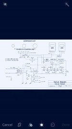
Hello all, I’ve attached a schematic of a tube tester I completed, it’s only for receiving tubes. A few changes I’ve made to tester, was adding a varic to keep the plate and screen supplies accurate, put ferrite beads on all tube sockets, put a 100uh inductor for parasitic issues. It test tubes at DC static characteristics per tube manufacturer data. I would like to test dynamic characteristics, I have a calibrated hp 201C audio oscillator. I’ve read some tube testers use a 1khz at 100mv signal. Can I just inject the test signal into tubes under test of course with the bias voltage? Will there be any impedance issues between the oscillator and the tubes being tested? Notice in the schematic there is no plate resistor in the circuit, will one be required? I’m building this for interest and learning. Any advice will be appreciative. Thanks
Attachments
I wouldn't use the variac, but rather perhaps just regulated supplies.
If you want to test dynamic characteristics, a load will be required.
To keep things simple, consider testing tubes as triodes. A selectable load of 100, 1000, 10000, and 100000 ohms will get you a decent selection. If you have a regulated power supply that can go from 300-600V, all the better! A negative bias supply will make things easier too. I'd recommend getting one of those cheap bench supplied on eBay as a bias supply. You can also put six AAA batteries in series, then a few 9V in series with that to get -1.5V, -3V, -4.5V, -6V, -7.5V, -9V, -18V, -27V, -36V (add more 9V if you need more bias voltage). Don't forget a grid leak resistor and input cap to keep your generator happy.
For a tube like a 12AX7, use the 300V supply, the 100K load, and dial up 1.5V of bias, then send the 1khz signal in and see what comes out.
Last edited:
Thanks Audiowize for the advice. Late response back on the thread, I had auto accident. One question about the load resistors, would the different values be for different tube types? By the way, my tester has a bias voltage from 0 to -80vdc on the tester. For dynamic characteristics, don’t mean to sound ignorant, what am I measuring, DC plate current, AC plate current, are the AC voltage output across the load resistor? Thanks for your time.
David
David
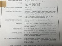
The soviet L3-3 tube tester works in the following interesting way:
There is a Wien bridge oscillator whose output is fed into a precision devider. this divider is used to adjust the sensitivity of the circuit.
The anode regulator has a 445 Ohm 0.1% shunt in the feedback loop, hence it keeps the output voltage at a fixed point, however in front of the resistor an AC signal is picked off and fed into a two stage bandpass filter that drives the panel meter.
During S calibration the 450mV signal is fed directly into the bandpass filter and the gain of the filter is adjusted to the calibration mark.
Due to the nature of the tester the the accuracy comes from the high stable anode shunts and S calibration resistors. Other components influence the drift but not the absolute accuracy
Schematic here:
http://www.jacmusic.com/Tube-testers/L3/Schematics-Versions/MM-Circuit-Diagram-L3-3.jpg
Im currently thinking of building a modular tube analyzer using the same principle, however it is to have switchmode pre regulators, and solid state lineair regulators. All fed from a 24V bus.
- Status
- This old topic is closed. If you want to reopen this topic, contact a moderator using the "Report Post" button.