I have a Yaqin MS-20L integrated amp (EL34). I installed a switch so I could disable/enable the negative feedback circuit at will. I like the sound with it off when using triode mode. I was thinking of taking out the switch and installing a stepped attenuator in it's place.
I have a 6 position switch that will do the trick and wondered what resistor values to try. The 1st position will be the factory setting and the 6th will be no negative feedback at all. So I will need 4 resistors for positions 2,3,4 and 5. Ideally the amount of attenuation would be linearly distributed from 1 through 6.
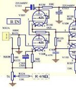
I attached part of the schematic, ignore the red drawing that is for something else. I will be putting the attenuator resistors in series with R110 & R124 (15kohms) to increase the resistance and lower the amount of feedback.
I was a CET back in the 70s but am NOT an engineer so I would like some advise on what resistor values to try in order to accomplish this.
Thanks,
David

I have a 6 position switch that will do the trick and wondered what resistor values to try. The 1st position will be the factory setting and the 6th will be no negative feedback at all. So I will need 4 resistors for positions 2,3,4 and 5. Ideally the amount of attenuation would be linearly distributed from 1 through 6.
I attached part of the schematic, ignore the red drawing that is for something else. I will be putting the attenuator resistors in series with R110 & R124 (15kohms) to increase the resistance and lower the amount of feedback.
I was a CET back in the 70s but am NOT an engineer so I would like some advise on what resistor values to try in order to accomplish this.
Thanks,
David
Why not like this, so you can change from no to max FB.
Mona
I thought about a pot but prefer steps.
Hmmmmm....
You got me to thinking, I have an extra ALPS blue 50k dual from another project. Throwing that in there would a lot easier.
Last edited:
Set your signal generator at 500Hz (so your DVM can read the AC signal) 1Vrms and input to the unit. Measure the voltage across the load with the feedback resistor in place and record it. The gain will be the output voltage since the input is 1Vrms. Measure the voltage across the load open loop, e.g. with no feedback and record it. Now use the Decibel calculator to compute the amount of NFB by comparing the open loop gain in dB with and without FB. Working backwards with the calculator compute the output voltage for -3dB, -6dB, and -12dB. Using a pot greater in resistance than the original feedback resistor, dial in each of these output voltages power down and measure the resistance at each voltage. Use these resistance in your switch.
- Status
- This old topic is closed. If you want to reopen this topic, contact a moderator using the "Report Post" button.