@ballpencil
Thanks for that, I wasn't familiar with Thevenin's theorem.. though it seems to be in the same vein as those of Kirchoff (and Jacoby) for that matter - semi common-sense stuff.
But I'm not sure how to draw the triode model in a Thevenin diagram - due to my simplistic mental model** of the triode, it ends up being drawn as just another resistance in series with the P and K circuits. How should it be drawn, such that the parallel relationship with rp is +clearly+ established?
(** I tend to view most tubes as "voltage-controlled rheostats". That is, they behave much like a rheostat, a variable resistance, where the position of the shaft (wiper) of the rheostat is controlled purely by the voltage on the grid. This is a functional model for tech work, but obviously it fails at this point.)
ETA: I noticed the comment about voltage vs. transconductance amplifiers - in terms of the series vs. parallel model. Once more, I don't grasp the difference in this instance..
When you draw the Thevenin equivalent of a triode gain stage, it will be clear what you said applies.
Thanks for that, I wasn't familiar with Thevenin's theorem.. though it seems to be in the same vein as those of Kirchoff (and Jacoby) for that matter - semi common-sense stuff.
But I'm not sure how to draw the triode model in a Thevenin diagram - due to my simplistic mental model** of the triode, it ends up being drawn as just another resistance in series with the P and K circuits. How should it be drawn, such that the parallel relationship with rp is +clearly+ established?
(** I tend to view most tubes as "voltage-controlled rheostats". That is, they behave much like a rheostat, a variable resistance, where the position of the shaft (wiper) of the rheostat is controlled purely by the voltage on the grid. This is a functional model for tech work, but obviously it fails at this point.)
ETA: I noticed the comment about voltage vs. transconductance amplifiers - in terms of the series vs. parallel model. Once more, I don't grasp the difference in this instance..
Last edited:
But I'm not sure how to draw the triode model in a Thevenin diagram - due to my simplistic mental model** of the triode, it ends up being drawn as just another resistance in series with the P and K circuits. How should it be drawn, such that the parallel relationship with rp is +clearly+ established?
Get yourself a copy of either the 1st or 2nd edition of "Basic Electronics for Scientists", by James Brophy. Prof. Brophy shows both the Thevenin equivalent for triodes and the Norton equivalent for pentodes. Of course, all sorts of other highly useful info. can be found in the text.
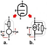
1) Thevenin and Norton models of the tube itself.How should it be drawn, such that the parallel relationship with rp is +clearly+ established?
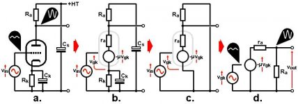
2) Whole gain stage rendered using the Thevenin model. In d. you can see how Ra is effectively in parallel with the whole tube.
Now try the same but starting with the Norton model.
Attachments
@Merlinb
Thanks for those illustrations, but they do leave some questions..
In the Thevenin diagram (LH side), what is represented by symbol "-muVgk"?
Should I read this as "1/(mu*Vgk)" or is it "-(mu*Vgk)" - where mu = amplification factor and Vgk = voltage between plate & cathode.
Thanks for those illustrations, but they do leave some questions..
1) Thevenin and Norton models of the tube itself.
In the Thevenin diagram (LH side), what is represented by symbol "-muVgk"?
Should I read this as "1/(mu*Vgk)" or is it "-(mu*Vgk)" - where mu = amplification factor and Vgk = voltage between plate & cathode.
In the Thevenin diagram (LH side), what is represented by symbol "-muVgk"?
It is a voltage generator that amplifies the grid-cathode voltage (vgk) by the amplification factor mu, and also inverts it. So the minus sign can be associated with either the vgk or the mu, it doesn't matter.
-mu*Vgk
-vgk*mu
-(vgk*mu)
Alternatively, you can remove the minus sign altogether if you reverse the direction of the voltage arrow, although I always find that a bit more confusing to visualise!
Last edited:
Some obvious nails still not hammered down...
Tube plate "impedance" is NOT a "complex impedance" (in the audio band).
It is the resistance for SMALL "dynamic" variations around a given point.
Yes, we often call our "dynamic" audio swings "AC", but AC Impedance is generally considered something else (stuff with major C and L too large to ignore).
In ballpencil/Merlin's image post #6, the from-zero resistance at "A" is 220V/1.5mA or 147K. But for *small* variation around "A" it is near 56K.
This 3:1 ratio comes from the general curve shape and is roughly true for most naked triodes. It won't always be "3" but dynamic R is almost-always less than static (op-point) apparent R.
> rp is one of the three dominant / salient parameters along with mu and Gm.
I am so glad you did not say "constants".
Rp and Gm vary roughly as square-root of current (I^0.5 in many hot-rod tubes, I^0.33 for ideal Child's Law tubes). So not constant.
Mu OTOH "can" be computed with a ruler. It is simple geometry. Oh, well, OK, in "real" tubes the Mu falls at very high current as the cathode-grid space gets crowded, and at low current when the main path cuts-off and sneak-paths of lower Mu become apparent. But most straight-wound tubes at most rational op-points will have a very steady Mu and very near the traditional datasheet values (which were always +/-10% or more).
So if you know Mu and know a Gm at your specific op-point, you can figure Rp. Since Gm can be worked very simply with a Cathode Follower's voltage gain, it is not necessary to dink-around with high plate impedances to get Rp.
Also note that Rp and Gm scale together, while Mu varies very little. So a slop on one gives a complementing slop on the other, and Stage Voltage Gain changes very little. Replace a 12AX7 with a 6F5 (earlier form of lower performance, still Mu=100), in a typical circuit, gain changes hardly at all.
> a classic 'impedometer' circuit..
For a "live" (current flowing) tube, you must have other elements to get the current in and out. If these could be infinite impedance, the answer is under the needle. In practice there are (at least were) no infinite-R DC paths, so you have to know and subtract the DC leaks.
And yes, the plate resistanCE and plate resistOR are parallel through the power supply.
Take 12AX7 in Fender form. Plate resistor is 100K. For 350V B+ the op-point happens to be very-near a Datasheet condition, says Rp=63K. Assume cathode resistor is fully bypassed. The output impedance (easily measured) is pretty near 39K. The bias point 250V 1mA looks like 250K from zero. Dynamic Rp 62K alone is 1/4 of op-point apparent resistance. Working-stage Zout of 39K is about 1/6.4 of op-point apparent resistance.
I've measured a lot of stuff, but I have never had a hankering to measure Rp.
In pentodes, there is "NO!" audio case where you care. The DC-flowing paths (or transformer parasitics) will overwhelm the internal vacuum effective resistance. {Pentode Rp does become important in RF(IF) tuned circuits, which can have low DC impedance with large 455KHz resonant impedance. (Tube Rp limits the Gain and Q you can get in one radio stage.)}
Pentode curves_ rp
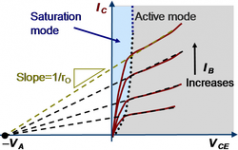
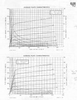
Bipolar transistors have an effect in their collector ("plate") curves called the "Early" effect (James M. Early), where the dynamic resistance can be related to an "Early" voltage on the negative collector ("plate") V axis. It is related to a modulation of the transistor base width. (see 1st graph below)
It turns out that Mosfets also have a similar effect, related to modulation of channel length. And is sometimes related as an "Early" effect also.
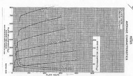
And so do pentodes!
(see 6DQ5 curves below)
Since us vacuum heads like to be somewhat contrarian versus the SS world, we could call ours the "Late" effect. The slope of the plate curves is of course just the plate rp. The negative voltage where the plate curve assymptotes meet (the "Late V") is different depending upon tube type, but once known, could be quite helpful in calculating the rp for any operating point. Curves for the 6LG6 are shown also for a case of a somewhat higher "Late V" spec tube. An Infinite "Late V" spec would correspond to pentodes that were perfect current sources (horizontal plate curves).
Note: near the plate curve knees, the simple relation is distorted due to high screen current subtracting out.
----
This same type of relation can also be generalised to triode curves. Explaining the "roll-over" effect seen at higher plate V. High "Late V" triodes would have very little plate curve "roll-over" effect. (can look at the rolled triode curves toward higher plate V as magnified versions (both axis's) versus the triode curves at lower plate V.)
An interesting question then is whether the "Late V" spec for pentodes has any connection to the "Late V" spec for triodes when triode configured. Some math work needed yet.
..
Bipolar transistors have an effect in their collector ("plate") curves called the "Early" effect (James M. Early), where the dynamic resistance can be related to an "Early" voltage on the negative collector ("plate") V axis. It is related to a modulation of the transistor base width. (see 1st graph below)
It turns out that Mosfets also have a similar effect, related to modulation of channel length. And is sometimes related as an "Early" effect also.
And so do pentodes!
(see 6DQ5 curves below)
Since us vacuum heads like to be somewhat contrarian versus the SS world, we could call ours the "Late" effect. The slope of the plate curves is of course just the plate rp. The negative voltage where the plate curve assymptotes meet (the "Late V") is different depending upon tube type, but once known, could be quite helpful in calculating the rp for any operating point. Curves for the 6LG6 are shown also for a case of a somewhat higher "Late V" spec tube. An Infinite "Late V" spec would correspond to pentodes that were perfect current sources (horizontal plate curves).
Note: near the plate curve knees, the simple relation is distorted due to high screen current subtracting out.
----
This same type of relation can also be generalised to triode curves. Explaining the "roll-over" effect seen at higher plate V. High "Late V" triodes would have very little plate curve "roll-over" effect. (can look at the rolled triode curves toward higher plate V as magnified versions (both axis's) versus the triode curves at lower plate V.)
An interesting question then is whether the "Late V" spec for pentodes has any connection to the "Late V" spec for triodes when triode configured. Some math work needed yet.
..
Attachments
Last edited:
Note 2:
Getting an exact meeting point for the plate curve assymptotes to find the "Late V" -MAY- require a re-scaling of the plate current axis (by like 2/3 power law or 0.5 law, ie Sqrt) due to the 3/2 (or typically up to 2.0) Child's (power) Law. (to un-do the non-linearity)
Actually, the tube curves shown above (6DQ5 and 6LG6) don't seem to need the re-scaling. Guess I'll have to eat those words. So it may be very simple indeed to derive the "Late V".
Alternatively,
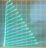
Twin (Crazy) Drive provides near linear (constant) gm for a pentode, so no power law re-scaling should be necessary to find the "Late V" spec for a tube this way. Take a look at the EL509/40KG6 Twin drive curves below to see this. ("Late V" about -500 V, except for the lowest current curves )
(Needs to be plotted in MathCad to determine if some power law re-scaling would help convergence.)
Getting an exact meeting point for the plate curve assymptotes to find the "Late V" -MAY- require a re-scaling of the plate current axis (by like 2/3 power law or 0.5 law, ie Sqrt) due to the 3/2 (or typically up to 2.0) Child's (power) Law. (to un-do the non-linearity)
Actually, the tube curves shown above (6DQ5 and 6LG6) don't seem to need the re-scaling. Guess I'll have to eat those words. So it may be very simple indeed to derive the "Late V".
Alternatively,
Twin (Crazy) Drive provides near linear (constant) gm for a pentode, so no power law re-scaling should be necessary to find the "Late V" spec for a tube this way. Take a look at the EL509/40KG6 Twin drive curves below to see this. ("Late V" about -500 V, except for the lowest current curves )
(Needs to be plotted in MathCad to determine if some power law re-scaling would help convergence.)
Attachments
Last edited:
- Status
- This old topic is closed. If you want to reopen this topic, contact a moderator using the "Report Post" button.
- Home
- Amplifiers
- Tubes / Valves
- Measuring rp of triodes (and pentodes, for that matter)