Dear all, i finally finished my 6v6 parallel push pull amplifier.
They are set up as mono blocks, and have two identical cirquits on them, see schematic for single cirquit.
OPT is edcor cxpp50w 3.4k
I am currently facing some issues with this set up.
- humm even without input plugged in
- no sound or only very low volume behind the humm
- one of the 6v6 sections show massive overheating, the upper end of the heater section in the tube glows completely, while the other section (the second cirquit, fed by the same transformer) does nit do that. It looks like some kind of leakage or so.
Is there anybody out there who can check the schematic for mistakes (of course i will also need to check the soldering and placing of components)
I will post a picture of the amp later
Thanks for your help
Attachments
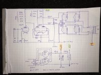
6SN7 anode resistors are about 20x what they should be.
Ditto. a 47k would be better, unless you have a huge supply voltage or are intentionally starving it of current for some obscure reason...
Get a picture of the bottom of the chassis for us, an actual look at the wiring would help.
Fire up the amp without the output tubes in place, B+ disconnected from the output transformer, and check the voltage you get at the sockets for the 6V6 tubes. verify that the screens , grids, anodes, cathodes, and filaments are correctly wired.
Did you choose the parts values yourself, or is this someone elses design?
Last edited:
What is that strange G2 connection on the lower right 6V6? Just a typo?
G²
You've got G2 on that section wired as the cathode. So if wired as per your schematic, that would explain a lot.
Thanks for all the replies
- the g2 is a typo, correct, sorry for the confusion caused
- i chose the resistor values from an old rca manual i found on the net, it was about maximum voltage gain... Probably the wrong way to go
- i will connect the cathodes of the 6v6 differential output pair
- replace the 6sn7 anode resistors with a 47k
Is this the same for the 6sq7 (according to the manual, the values on the schematic schould lead to a maximum gain of around 60
I just found out that one of the opt clickers or hums when the voltage climbs after switching on.
The hum is audible when lustening on the opt.
When i disconnected the opt from b+, it got away and the voltage of b+ climbed to 487v (this voltage increase from b+ with opt of 283 to without opt 487v seems massive, could this be due to the fact that there are two opts in each amp, and their load is too high for the power transformer?
Greetings from FixitLand!
No bias supply is shown for the 6V6s. What is the bias voltage?
I would think 120 ohms cathode resistance for **all four** 6V6s is in order. (You have 120 ohms for each pair, and if parallelled you then have 60 ohms.) You might check the voltage across your parallelled cathode resistors. I seem to recall finding about 250 ohms worked well for a single push-pull pair of 6V6s. (It's said that there's no such thing as a bad-sounding 6V6 amp.)
Is there a reason you used several individual resistors to make up the anode resistors for the 6SQ7 and 6SN7? Perhaps that's what you have in stock. I concur with the previous poster that you should lower the 6SN7 anode load; ditch the 470Ks. The anodes' quiescent voltage should be at 1/2 the B+ or slightly higher, approximately 160-170 V would be good.
Also be aware that the anode voltage of the 6SQ7 has an effect on the 6SN7 voltages. It too should be run at about 1/2 B+. The value of its cathode resistor can have effect on this too. Per the General Electric 6SQ7 data sheet, to get a gain of "around 60" with 510K anode resistor and 300 V B+ supply, the cathode resistor should be 6200 ohms, over four times the 1.5K you have specified. That gain figure is specified at 5% total harmonic distortion. Don't expect miracles!")
The input is DC-coupled. This is fine if you can be certain that any audio source you might ever connect to this amplifier has no DC component. There's also no volume control, which I would assume you have in a preamp.
I would also think a single 5AR4 rectifier would be more than sufficient. Two seems overkill. The Edcor XPWR 149 transformer's 5V winding is rated for 3 A, which is NOT sufficient to power two 5AR4s with their 1.9-ampere heaters. The typical DC output current for a 5AR4 with capacitor-input filter and 450 VAC per plate input is 225 mA; with choke-input (as you have drawn) it is 250 mA.
Good luck, and have lots of fun with your amp project!
Take care,
—
J. E. Knox "The Victor Freak"
No bias supply is shown for the 6V6s. What is the bias voltage?
I would think 120 ohms cathode resistance for **all four** 6V6s is in order. (You have 120 ohms for each pair, and if parallelled you then have 60 ohms.) You might check the voltage across your parallelled cathode resistors. I seem to recall finding about 250 ohms worked well for a single push-pull pair of 6V6s. (It's said that there's no such thing as a bad-sounding 6V6 amp.)
Is there a reason you used several individual resistors to make up the anode resistors for the 6SQ7 and 6SN7? Perhaps that's what you have in stock. I concur with the previous poster that you should lower the 6SN7 anode load; ditch the 470Ks. The anodes' quiescent voltage should be at 1/2 the B+ or slightly higher, approximately 160-170 V would be good.
Also be aware that the anode voltage of the 6SQ7 has an effect on the 6SN7 voltages. It too should be run at about 1/2 B+. The value of its cathode resistor can have effect on this too. Per the General Electric 6SQ7 data sheet, to get a gain of "around 60" with 510K anode resistor and 300 V B+ supply, the cathode resistor should be 6200 ohms, over four times the 1.5K you have specified. That gain figure is specified at 5% total harmonic distortion. Don't expect miracles!
The input is DC-coupled. This is fine if you can be certain that any audio source you might ever connect to this amplifier has no DC component. There's also no volume control, which I would assume you have in a preamp.
I would also think a single 5AR4 rectifier would be more than sufficient. Two seems overkill. The Edcor XPWR 149 transformer's 5V winding is rated for 3 A, which is NOT sufficient to power two 5AR4s with their 1.9-ampere heaters. The typical DC output current for a 5AR4 with capacitor-input filter and 450 VAC per plate input is 225 mA; with choke-input (as you have drawn) it is 250 mA.
Good luck, and have lots of fun with your amp project!
Take care,
—
J. E. Knox "The Victor Freak"
Greetings from FixitLand!
Just had another quick thought: The 6SQ7 triode has a µ (mu) of 100, which is good, but it is not what's generally considered a "hi-fi" tube (plus there are two wasted diodes). Since you have an octal tube already, you might consider switching to a 6SF5 metal triode. It has the same mu, and (at least given the examples I've seen) has a spiral-wound heater, which can give it some resistance to hum. Plus, being that it's a metal tube, it's shielded. (There is a 6SF5-GT glass version as well.) I have used the 6SF5 in an experimental phono preamp, with excellent results.
It's worth a look: VinylSavor: Tube of the Month : The 6SF5
Regarding hum: The heater supply can be lifted a few dozen volts above ground, to further reduce heater-induced hum. The Edcor XPWR 149 transformer has TWO 6.3 V heater windings; one of them is center-tapped and rated for 1.2 A. Use that winding for the 6SQ7 (or 6SF5) and 6SN7 heaters, and tie the center tap to a voltage divider (two resistors) sized to give 40-60 V or so. Doesn't need any current; it's just a voltage reference. You have 291 V B+; if you take a 220K and 47K resistor in series, from B+ to ground (220K to B+, 47K to ground), they'll draw just a hair over 1 mA, and you'll have about 51.225 V across the 47K resistor. Connect a film capacitor across the 47K resistor (value isn't critical; 0.1 µF works), and connect the heater winding's center tap to the resistor junction.
The 6SN7 runs in this circuit with its cathodes at a fair amount of DC voltage. There is a limit to the heater-to-cathode voltage; biasing the heater supply positive alleviates the possibility of H-K leakage or short.
Maybe it wasn't such a "quick thought."
Take care,
—
J. E. Knox "The Victor Freak"
(...) - replace the 6sn7 anode resistors with a 47k
Is this the same for the 6sq7 (according to the manual, the values on the schematic schould lead to a maximum gain of around 60
Are you suggesting that the 6SN7 should use the same anode (plate) resistor values as the 6SQ7? Just to be clear - the 6SN7 is dual low-medium mu triode, with a gain of ~20. The 6SQ7 has a single triode section that approximates a 12AX7 section, with a mu of ~100.
The two tubes require very different anode loads - the 6SQ7 would tend to use 220-470K while the 6SN7 would tend to use 50-100K (these are just comparative ranges). Cathode resistors would be different, also - point is, the only similarity between them is that they are both small-signal AF triodes.
(The 6SQ7 also has a pair of diodes, common to the cathode of the triode section. The tube is meant for AM radio use, with the triode being the AF amp, and the diodes acting as AM detector and AGC rectifier.)
Last edited:
the 6SQ7 would tend to use 220-470K
The plate curves actually look pretty decent - properly loaded.
Where did you return the two 470k grid resistors on the four 6V6s?
They seem to be just floating. You need to return that junction of those two resistors to ground.
With grids that are floating, tubes can either be shut off; or can turn on very hard even to the point of self destruction.
If you have a 6V6 that is red plating, it may be destroyed. Also, if there is not a high enough voltage rating on the cathode bypass caps, they might be destroyed (like when one of the tubes is over conducting and red plating.
Yes the 6FQ7 plate resistors are way to large.
You starved both the 6FQ7, and as noted earlier the 6SN7.
You do not need 2Meg Ohms as the input grid resistor. 100k Ohms would be better for most applications.
It looks like you have 420 Ohms per two cathodes, and 30uf per 2 cathodes.
I am a fan of using four resistors, and four bypass caps.
You can individually self bias each 6V6.
One reason is that you can easily measure the current of each 6V6 (current = Volts/Ohms).
Another reason is that without matched currents, the output transformer may distort or saturate prematurely.
There is a possibility that tube currents do not match when you tie all their cathodes together.
You might start with 810 Ohms and 100uF @ 63V. There probably will not be enough current with 810 Ohms, I merely multiplied 420 by almost 2.
(where did you get the 420 Ohm value, from another amp, or calculate yourself)?
620 Ohms might be a better place to start.
It looks like you may have quite a bit to do to get the amp working, and maybe even more to optimize it.
Was the schematic from a tested circuit, or modified, or just put together?
The plate curves actually look pretty decent - properly loaded.
Curves for the triode section of the 6SQ7?
I don't doubt they look decent.. again, that triode is essentially 1/2 of a 12AX7. But the two are constructed very differently - 12AX7 typically use a flat waffle-plate design, whereas the 12/6SQ7 typically have a cylindrical plate. That aside, the parameters are nearly identical, per my recall.
The SQ7 series also has the advantage of the octal envelope and base, which tends to keep things a bit more quiet and stable.
Where did you return the two 470k grid resistors on the four 6V6s?
Seems to be grid leak biased - bias circuit returned to ground. Secondary issue at this point is that it appears to be returned to the first power supply charging cap, which could be noisy.


Sheldon,
I may have missed something, the schematic is a little blurry on my monitor, or because of my eyes.
I believe the schematic in post #1 shows the two 470k grid resistors for the four 6V6s going down the page, and with a half-circle jump over the horizontal ground wire, than connecting to nothing more than the words "6V6 Bias". That is floating, not Bias.
That is why I asked if they were in fact wired differently than the schematic.
It may only be a drawing error, but it is important, suppose it is actually wired that way.
I believe the two 420 Ohm resistors to the 6V6 cathodes in the same schematic are Self Bias resistors.
I think I remember the term Grid Leak, and Grid Leak Bias, being applied to early RF circuits:
Either the signal was applied to a paralleled RC, and paralleled RC to the grid;
Or the signal was applied to C, C to R, and that RC junction to the grid, and the other end of R to ground. I think that is also called RC coupling.
That is a good point about the hum:
If any grid return resistors are connected to the first filter cap negative terminal, that is a great way to get some very nasty hum, with lots of harmonics because the ripple current is greatest there, and does not resemble a full wave rectified sine.
And yes, the first filter cap return should be in a short length local loop with the HV center tap. Then it can be wired from there to the separate central star ground, where the grid resistors are returned.
I use choke input supplies when possible. But care has to be taken there, including the HV center tap to the cap that follows the choke (another short loop) that then is connected to the separate central star ground. But even that has the problem of the magnetic spray that comes from the input choke (it is swinging more voltage in a LCRC, than in a CLC supply).
Hopefully, we can get that 6V6 amp up and running smoothly.
- Status
- This old topic is closed. If you want to reopen this topic, contact a moderator using the "Report Post" button.
- Home
- Amplifiers
- Tubes / Valves
- No output sound from 6v6 parallel push pull