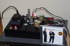
I have built this amplifier for a friend. It was originally a Zenith phonograph amplifier. The only parts I kept are the power transformer and the tubes, everything else is new. I did decide to upgrade from the original Zenith 6X4 to a 6CA4 rectifier. A bit less voltage drop and I didn't want to run near the edge of the envelope on the 6X4.
I based the voltage amplifier on the "4S Universal Preamplifier" schematic that I found here:
4S Universal Preamplifier for 12A*7 Tubes
I based the output section on several schematics I found on the web; they all seem pretty much the same, but I mostly used this one:
7-pin MT tube 6AQ5 single vacuum tube amplifier
I am attaching my final schematic as well.
The amp is built, and it sounds pretty good to me, with some minor quibbles. I lack advanced testing tools, but the voltages I have measured are as follows:
12AX7A Anode - 98V
12AX7A Cathode - .8V
6AQ5A Anode - 233V
6AQ5A Cathode - 12.5V
The amp runs fairly cool; several hours playing music result in a PT that is hot but not too hot to touch, a cool chassis, and of course the 6AQ5A tubes are as hot as the surface of the sun, but that's pretty much how they are by design, I believe. The 12AX7A remains cool, the 6CA4 is hot but not terrifically so.
As described in the "4S Universal Preamp" design, this does seem to work reasonably well with any of the 12A*7 family. I am currently running with the 12AX7A, but it seems the 12AU7A is very nice for quiet listening to jazz and classical music.
I've tried the amp with different values for the NFB resistor, varying from 1K to 6.8K (currently using 6.8K) and with the cathode resistor on the 12AX7A bypassed and non-bypassed. Currently bypassed, but I could go back to non-bypassed again; it's not bad either way, just more gain with the bypass.
I originally had the volume pot in front of the 12AX7A, but I got horrible grinding noises with changes in volume, and I was using a good qualify pot; I even bought an expensive ALPS but it made no difference. Putting it behind the 12AX7A really quieted it down - no complaints at all now.
The minor quibbles I am having are these.
First, I am getting older and have some hearing loss at high frequencies, but this amp seems to have a bit more treble that I would like. I keep wanting to turn down the treble, but of course there is no tone control. If I run this with an external preamp, I *do* turn the treble down a bit.
Second, bass is not all that. Granted that these output transformers are limited, and I do not expect either true 'hi-fi' or extended bass output, but I've used them on other amps and gotten what I think is better bass. I can live with the bass that is present, but if I could get even a tiny bit more, that would be good.
Third, there is a hum. I don't know if it is 60Hz or 120Hz to be honest. It is present as soon as the output tubes warm up, and it does not vary with volume or become louder or softer. It's not much, but it's a tad more than I'm used to with previous amps I've built. I'm not sure if I have too much ripple on my B+ or if the AC heaters are causing the issue. I have tried to practice good wire management.
So I am open to your review and suggestions. I am thinking maybe I need more B+ filtering? And wondering about the .47 value of the coupling capacitor and whether or not this is having an effect on the 'too much treble' response I am currently getting.
Thank you!
Attachments
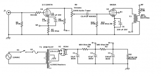
R₉, at 100 kΩ, is going to 'drain away' 50% of the gain of the first stage '12ax7'.
It would be better to use something like a 250 kΩ audio taper. Less loss.
Since B++ will be running at such low current, R2 (680 Ω) will hardly be doing much filtering. It doesn't need to be 5 watts, either. a couple of milliamps to both halves of the 'ax₇', right?…
E = IR = 0.002 × 680 = 1.36 V.
P = IE = 0.002 × 1.36 = 2.7 milli-watts.
But if you got a bag of 5 watt-ers, go for it.
However, the pair (stereo? or mono block?) of AQ's are each going to draw what, about 70 to 100 ma? Let's call it 200 ma for both Same equations:
E = IR = 0.2 × 680 = 130 volts.
P = IE = 0.2 × 130 = 26 watts.
Now the 5 watt 680s look a bit under-specified. 1/4 that (6 watts) for mono block. 1/2 that if lower per-AQ operating point...
What are the operating points, anyway? (AQ's)
GoatGuy
Last edited:
R₉, at 100 kΩ, is going to 'drain away' 50% of the gain of the first stage '12ax7'.
It would be better to use something like a 250 kΩ audio taper. Less loss.
Since B++ will be running at such low current, R2 (680 Ω) will hardly be doing much filtering. It doesn't need to be 5 watts, either. a couple of milliamps to both halves of the 'ax₇', right?…
E = IR = 0.002 × 680 = 1.36 V.
P = IE = 0.002 × 1.36 = 2.7 milli-watts.
But if you got a bag of 5 watt-ers, go for it.
However, the pair (stereo? or mono block?) of AQ's are each going to draw what, about 70 to 100 ma? Let's call it 200 ma for both Same equations:
E = IR = 0.2 × 680 = 130 volts.
P = IE = 0.2 × 130 = 26 watts.
Now the 5 watt 680s look a bit under-specified. 1/4 that (6 watts) for mono block. 1/2 that if lower per-AQ operating point...
What are the operating points, anyway? (AQ's)
GoatGuy
Thank you, good suggestions! I did indeed use a 5W 680 Ohm resistor for B+ and B++ because I had a big bag of them. Seemed better to be safe than sorry. But if the B+ resistor should be a higher wattage, I have a 7W 680 Ohm I could put in there.
Yes, this is a stereo SE design. The schematic shows only one channel, but both are identical.
I can get a 250K audio taper volume pot, thanks! I did not realize it would make that much of a difference.
As to the operating points, I confess I did not draw load lines or anything. I copied what I saw in the schematics I linked to above. Minor changes - 100 uF bypass capacitors instead of 33 uF. 330 Ohm cathode resistor on the 6AQ5 tubes instead of 300 Ohm (because I didn't have any 300 Ohm resistors of sufficient wattage). I was hoping they would not make a huge difference in operation.
The 300 Ω or 330 Ω resistor choice will not make a major (or even terribly minor) difference. ± 10%. That used to be the tolerance for a pretty good common-place resistor!
ALSO NOTE: the audio pot is running at some pretty high voltages (near B++). Myself? I'd put the darn thing on the other side of C5.
In fact, C5 doesn't need to be there 'as a resistor' at all. It could just be a 250 kΩ to 500 kΩ audio taper pot. Even higher net gain. Great control. The "safety" of running it at near-ground potential. This is why one RARELY sees potentiometers attached to B++ levels. They can short, you know … to the stem or the case of the lil' thing. And what if you are using awesome turned aluminum knobs?
Ouch.
Bad ouch.
While you didn't draw load-lines, you ought to be able to look back at your copied originals and determine what load-points they were working with. Franken-amps are FINE… provided you do the gross calculations (as I did) to confirm wattages and so on.
It ain't hard. Just remember
E = IR (Ohm's law)
P = IE (Baker's law) (that was a joke)
and
Z = 1/(2 π FC) (the impedance law for capacitors)
I'm not having the spare time to explain why, but it is darn useful as a 'pocket calculation' for determining capacitor values in a pinch.
GoatGuy
The 300 Ω or 330 Ω resistor choice will not make a major (or even terribly minor) difference. ± 10%. That used to be the tolerance for a pretty good common-place resistor!
ALSO NOTE: the audio pot is running at some pretty high voltages (near B++). Myself? I'd put the darn thing on the other side of C5.
In fact, C5 doesn't need to be there 'as a resistor' at all. It could just be a 250 kΩ to 500 kΩ audio taper pot. Even higher net gain. Great control. The "safety" of running it at near-ground potential. This is why one RARELY sees potentiometers attached to B++ levels. They can short, you know … to the stem or the case of the lil' thing. And what if you are using awesome turned aluminum knobs?
Ouch.
Bad ouch.
Thanks so much for your time. I do appreciate it very much.
I have never put the volume pot on the B++ side of the input tube before, but as I mentioned, I was getting some horrible scratchy noise when I adjusted the volume, and if I had any hair, I'd have been pulling it out - could not make the noise go away! The "4S Universal Preamp" I copied from put it on the high side of the 12A*7 and when I did that, the noise while adjusting the pot went away. I can put it back in front of the tube again, but if the noise comes back, I don't know what to do about it! Very frustrating!
I thought the .47 cap at C5 was for safety as well as coupling - but you say it is not needed at all? Most of the amps I've built (not a lot, but more than a couple) have generally had a .01 uF cap there, which is why I was questioning the .47 uF found in the schematic I copied from.
I will try to go back and figure out the operating points for the 6AQ5 tubes, thank you.
WAIT… I made a typo.
C5 needs to be there.
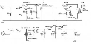
R10 can become the audio taper pot.
I was typing too fast.
GoatGuy
V E R Y I M P O R T A N T !
LOL! OK, got it! Put the audio taper pot (250K) after C5 in place of the 470K grid leak resistor, right?
see diagram, above
Got it, thanks so much for your time!
Goatguy has given you some good advice. I would certainly place the audio taper after C5. I would keep R9, which is nice in case the wiper connection in the audio taper fails.
I would keep R2 at 5W – it is true the 12AX7 does not pass much current once the amp is running, but C3 has to be charged at startup.
Torben
I would keep R2 at 5W – it is true the 12AX7 does not pass much current once the amp is running, but C3 has to be charged at startup.
Torben
Goatguy has given you some good advice. I would certainly place the audio taper after C5. I would keep R9, which is nice in case the wiper connection in the audio taper fails.
I would keep R2 at 5W – it is true the 12AX7 does not pass much current once the amp is running, but C3 has to be charged at startup.
Torben
Thanks to both of you! I have ordered a 500K stereo audio-taper pot from Parts Express and will place it after C5 as soon as it arrives. As you suggested, I will keep the grid leak resistors for the 6AQ5 tubes. With a 500K pot for the volume, should I increase the value of that resistor from 470K?
Tell me, do you think the value (.47 uF) of the coupling cap seems correct to you? I'm still not sure why I have an abundance of treble.
As to the hum...B+ ripple or heaters? I wish I could tell the difference between 60 Hz hum and 120 Hz hum, but I just can't seem to...
In the above post I meant R10 where I wrote R9, and If you increase the audio taper I would also increase R10 to 1MOhm.
I figured you meant that, and thanks for the advice on increasing the value of R10. You guys are a great help, thank you!
Hi.
Just looked at the schematic again. Why not place the volume pot at the front? Placing it inside the feedback loop is completely wrong. Or have I missed something? I would place it at the front and keep it at R=100k. The keep R10 at 470k.
exactly what i was about to say.. but then i took the time to re-read the original post.
Hi.
Just looked at the schematic again. Why not place the volume pot at the front? Placing it inside the feedback loop is completely wrong. Or have I missed something? I would place it at the front and keep it at R=100k. The keep R10 at 470k.
I originally had it in front. The problem was that any adjustment of the volume pot created huge scratchy noises as the pot was turned. I tried different pots - even an expensive Alps unit. I tried different value resistance pots. Nothing seemed to work.
I ended up putting it where it is now because that's where this put it:
4S Universal Preamplifier for 12A*7 Tubes
And I figured they know more than I do. When I moved it, the scratchy horrible noise from adjust the pot completely went away.
I had never done it this way before - but I have never needed to do it before. Not sure why the volume pot sounded so horrible in the 'correct' position, but it did, so when I moved it and it got better, I thought that was a good thing.
When the pot was on the 12ax7 input side, did you put grid leak resistor along with the pot, or just the pot? Grid leak resistor = that 470k resistor on the 12ax7 grid. Is there a DC offset on the source output?
Even if you choose to follow GoatGuy's suggestion on post #6, there should be a grid leak resistor also for the 6AQ5. You want to keep a constant reference for the grid which is not guaranteed if you use just the potentiometer. The wiper can lift off from the track anytime.
Even if you choose to follow GoatGuy's suggestion on post #6, there should be a grid leak resistor also for the 6AQ5. You want to keep a constant reference for the grid which is not guaranteed if you use just the potentiometer. The wiper can lift off from the track anytime.
When the pot was on the 12ax7 input side, did you put grid leak resistor along with the pot, or just the pot? Grid leak resistor = that 470k resistor on the 12ax7 grid. Is there a DC offset on the source output?
The 470K grid leak resistor was on the 12A*7 input when the pot was on the input, so yes.
As to DC offset on the source output, I don't know. I did test with multiple devices, including three different CD players and a turntable through an Aiwa dedicated pre-amp. All units work normally with other amplifiers.
Even if you choose to follow GoatGuy's suggestion on post #6, there should be a grid leak resistor also for the 6AQ5. You want to keep a constant reference for the grid which is not guaranteed if you use just the potentiometer. The wiper can lift off from the track anytime.
Understood and I will be increasing the size of the grid leak resistor on the 6AQ5 tubes from 470K to 1M as a result of changing the volume pot from 100K to 500K. I've ordered the parts and will install them this weekend, test, and report back.
I honestly do not understand why I was getting horrible scratchy noises from the volume pot when placed in the traditional location. I had a .01 decoupling cap in the line as well - I tried that both in front of the pot and behind the pot and in front of the grid of the 12A*7 tube inputs, didn't seem to matter.
I did NOT have a 10K grid stopper on the 12A*7 until after I moved the pot - I did both those things at the same time. Perhaps the grid stopper had something to do with it, but I never tested that theory. All I know is that the noise from adjusting the pot stopped when I move it to the back of the 12A*7 tube.
In searching Google, I have read several people who have reported similar issues with volume pots, but have never read of a satisfactory resolution. It seems they just give up and go away after awhile. If I had run into the issue before I cut a hole in my nice powder-coated chassis for a volume control, I might have just left it out entirely.
the noise is still there, it's just not being amplified by the 12AX7 ,just the output tube
i Have a 250k stock pot in an SX 3700 that is now virtually noiseless after placing the preamp before the pot. It's a combination of the pot has 10x the signal to work with and the gain after the pot is 10x less
This is good for a 40db improvement.
i Have a 250k stock pot in an SX 3700 that is now virtually noiseless after placing the preamp before the pot. It's a combination of the pot has 10x the signal to work with and the gain after the pot is 10x less
This is good for a 40db improvement.
Last edited:
StockTrader200, that's not actually accurate. ("not being amplified by the 12AX 7")
With a pot attached to B+, every time the wiper breaks contact with the swept resistance, potential drops to zero. Huge noise spike.
When a pot is attached to a DC blocking cap, to signal (and ground), then the 'sweeper break' can only momentarily drop the varying AC signal to ground. Much smaller noise.
TECHNICALLY the noise is still there. Just a different kind. It is especially noticeable in the 2nd case when one is using a sinusoidal source at full amplitude. Something low, like 30 or 40 Hz. Then the sweeper noise is apparent.
Just saying…
GoatGuy
- Status
- This old topic is closed. If you want to reopen this topic, contact a moderator using the "Report Post" button.
- Home
- Amplifiers
- Tubes / Valves
- Request review of my schematic