Dear tube gurus...
I'm in need of help 🙂
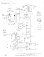
I've ordered a Yamamoto A08S amplifier kit directly from Japan.
I have built many kits and DIY projects in the past and have basic understanding of SS electronics, but this was my first tube experiment, and not a very good one unfortunately...
It seems like the assembly manual was translated from the Japanese text using google translate, and you can imagine how readable that is.
They also printed the manual using a standard ink-jet printer, with un-calibrated colors that don't match the wire colors...
You get the drift 🙂
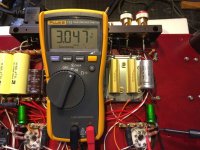
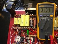
Anyway, after much frustration, I've managed to complete the kit it but I'm getting some DC voltages that are way off.
All AC voltages measure more or less OK.
However, for the DC voltages I get:
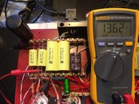
only 13.5VDC instead of 123VDC
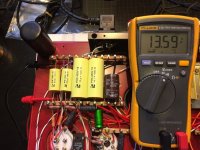
only 17VDC instead of 110-170VDC
and only 3.1VDC instead of 3.8VDC
I have checked and rechecked my wiring and I can't find anything wrong with the connections.
Of course, I have not hooked it up to speakers yet.
I have corresponded with Yamamoto about this issue, but it seems futile.
The language and time barriers (they take 3-5 days to answer) make it extremely frustrating, and they also seem not overly eager to help :-(
What I've done so far (following their advice) is to disconnect the Zener diodes, and to remove the 717 tubes, but the DC Voltages remain pretty much the same in either case.
If anyone here has an idea about what could cause that, I will be forever grateful!
Thank you in advance and have a wonderful day 🙂
Ami
I'm in need of help 🙂
I've ordered a Yamamoto A08S amplifier kit directly from Japan.
I have built many kits and DIY projects in the past and have basic understanding of SS electronics, but this was my first tube experiment, and not a very good one unfortunately...
It seems like the assembly manual was translated from the Japanese text using google translate, and you can imagine how readable that is.
They also printed the manual using a standard ink-jet printer, with un-calibrated colors that don't match the wire colors...
You get the drift 🙂
Anyway, after much frustration, I've managed to complete the kit it but I'm getting some DC voltages that are way off.
All AC voltages measure more or less OK.
However, for the DC voltages I get:
only 13.5VDC instead of 123VDC
only 17VDC instead of 110-170VDC
and only 3.1VDC instead of 3.8VDC
I have checked and rechecked my wiring and I can't find anything wrong with the connections.
Of course, I have not hooked it up to speakers yet.
I have corresponded with Yamamoto about this issue, but it seems futile.
The language and time barriers (they take 3-5 days to answer) make it extremely frustrating, and they also seem not overly eager to help :-(
What I've done so far (following their advice) is to disconnect the Zener diodes, and to remove the 717 tubes, but the DC Voltages remain pretty much the same in either case.
If anyone here has an idea about what could cause that, I will be forever grateful!
Thank you in advance and have a wonderful day 🙂
Ami
Attachments

I would start with the transformer and see whether the right voltages are coming out of that.
Then work forward until the voltages go wrong.
Then work forward until the voltages go wrong.
You haven't said whether the rest of the DC voltages are normal. Are they? If they're all low, then suspicion falls on the rectifier tube.
Hi Nigel and Mike,
Thanks for your prompt replies.
Sorry for not being 100% clear in my post.
Main AC Voltage (330V) and heater voltages check OK.
Rest of DC Voltages also check OK.
The only issue is with the 3 measurements that I've mentioned that are off by a factor of 10.
cheers,
Ami
Thanks for your prompt replies.
Sorry for not being 100% clear in my post.
Main AC Voltage (330V) and heater voltages check OK.
Rest of DC Voltages also check OK.
The only issue is with the 3 measurements that I've mentioned that are off by a factor of 10.
cheers,
Ami
Hi Ami67,
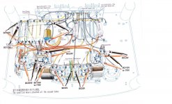
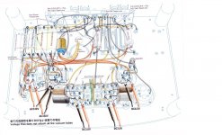
Removing zeners and 717 tubes should lead to app. 354V DC at the point that 123V DC should be measured. If indeed you get 354V at the first cap after the rectifier tube then check
carefully the network RWR84S6 and CPF3 and relevant caps. Hope this helps .Don't give up.
Removing zeners and 717 tubes should lead to app. 354V DC at the point that 123V DC should be measured. If indeed you get 354V at the first cap after the rectifier tube then check
carefully the network RWR84S6 and CPF3 and relevant caps. Hope this helps .Don't give up.
I would recommend trying another multimeter, the Vcheck feature on this meter seems to imply a relatively low input impedance which might be loading things down - does not matter when the node resistances are low, but might make a difference with some of the circuit points measured. I looked for an input resistance specification for this meter and was unable to find one.
Does it appear to function correctly otherwise?
Does it appear to function correctly otherwise?
Hi MagicBus,
Thanks for your prompt reply.
I have inspected the network once again and it seems to be wired correctly.
I see why the SG2 point should have 350V when the zener and tube are removed, and I have confirmed that nothing on that point closes the circuit to ground.
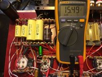
When I measure the voltage on both sides on the 100K resistor next to CPF3, I get ~350V on the rectifier side but when I attach the meter to the other side which leads to the 717 tube, It starts off displaying about 100V and quickly drops to 15V in about 10 seconds.
This makes me suspect my meter now...
It's a brand new Fluke 113, and it has the VChek LowZ function which I can't seem to turn off. I searched online and couldn't find any clue to that.
The Fluke manual says:
VCHEK
If a dc or ac voltage greater than about 3 V is present across the inputs
when the meter is set to VCHEK, the meter switches automatically to dc
or ac voltage mode and displays the voltage.
When VCHEK is activated, the meter has low input impedance (LoZ)
~3 kOhm. This load can alter the voltages in electronic control circuits. Do
not use VCHEK to measure voltage in circuits that could be damaged by
a 3 kOhm load.
Note: VCHEK can be effectively used to eliminate “ghost” voltages.
Could that be related to my issue?
Thanks again,
Ami
Thanks for your prompt reply.
I have inspected the network once again and it seems to be wired correctly.
I see why the SG2 point should have 350V when the zener and tube are removed, and I have confirmed that nothing on that point closes the circuit to ground.
When I measure the voltage on both sides on the 100K resistor next to CPF3, I get ~350V on the rectifier side but when I attach the meter to the other side which leads to the 717 tube, It starts off displaying about 100V and quickly drops to 15V in about 10 seconds.
This makes me suspect my meter now...
It's a brand new Fluke 113, and it has the VChek LowZ function which I can't seem to turn off. I searched online and couldn't find any clue to that.
The Fluke manual says:
VCHEK
If a dc or ac voltage greater than about 3 V is present across the inputs
when the meter is set to VCHEK, the meter switches automatically to dc
or ac voltage mode and displays the voltage.
When VCHEK is activated, the meter has low input impedance (LoZ)
~3 kOhm. This load can alter the voltages in electronic control circuits. Do
not use VCHEK to measure voltage in circuits that could be damaged by
a 3 kOhm load.
Note: VCHEK can be effectively used to eliminate “ghost” voltages.
Could that be related to my issue?
Thanks again,
Ami
Hi Kevin and thanks for your reply.
I just posted a reply to MagicBus suspecting the same thing and then saw your reply...
The meter functions perfectly otherwise, and all other voltages checked OK with it.
With LowZ it has about 3K impedance.
It could be that I was really chasing a ghost here 🙂
I will get another meter and try again.
Thanks a lot!
Ami
Hi Kevin and thanks for your reply.
I just posted a reply to MagicBus suspecting the same thing and then saw your reply...
The meter functions perfectly otherwise, and all other voltages checked OK with it.
With LowZ it has about 3K impedance.
It could be that I was really chasing a ghost here 🙂
I will get another meter and try again.
Thanks a lot!
Ami
3k is way too low checking high impedance tube circuit.
Get a decent meter with high input impedance. For the rest I agree with Nigelwright.
UPDATE:
Thanks to all that jumped in to help with good advice.
It turns out that it was indeed a multimeter issue.
I wrote Fluke support and it turns out that with this model (Fluke 113), there is no way to turn off the VChek LowZ.
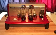
The amp is (and was) working fine and is now hooked up and breaking in.
It sounds PHENOMENAL.
With just 2 Watts per channel, it's not for every speaker, but with my >100db Zu Audio Druids, it sings even better than it looks 🙂 Attached is a photo of the finished amp.
Have a wonderful day and weekend!
Ami
Thanks to all that jumped in to help with good advice.
It turns out that it was indeed a multimeter issue.
I wrote Fluke support and it turns out that with this model (Fluke 113), there is no way to turn off the VChek LowZ.
The amp is (and was) working fine and is now hooked up and breaking in.
It sounds PHENOMENAL.
With just 2 Watts per channel, it's not for every speaker, but with my >100db Zu Audio Druids, it sings even better than it looks 🙂 Attached is a photo of the finished amp.
Have a wonderful day and weekend!
Ami
Attachments
- Status
- Not open for further replies.
- Home
- Amplifiers
- Tubes / Valves
- Need help troubleshooting Yamamoto A08S Kit build :-(