runeight said:How much gain do you need?
If you need gain, the design depends on how much you actually need.
I would be happy with unity gain. I know my options in transformers or solid state, so it is not a question of my thinking this is the path of least resistance. I think it would be a great, simple tube project that might just sound wonderful.
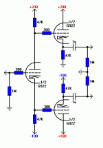
If you don't mind cathode followers (and I don't when they're biased correctly), you can try something like this. It's a simple split load phase splitter driving two CFs as output buffers.
It does need a few different supplies, but they're easy to make.
It does need a few different supplies, but they're easy to make.
Attachments
I think that halving the voltages would be sum-optimal, although 6922s don't mind low voltages too much. The performance, especially the THD, will likely suffer.
You can buy 120VAC Triad transformers really cheap. You would only need two of them to provide +/- 100V and the +200V could be had from a voltage doubler. You can even use VR tubes to regulate. 0B2 will regulate at about 108V. Close enough for this amp.
You can buy 120VAC Triad transformers really cheap. You would only need two of them to provide +/- 100V and the +200V could be had from a voltage doubler. You can even use VR tubes to regulate. 0B2 will regulate at about 108V. Close enough for this amp.
Hmmm, I think I can make do using multiple surplus transformers.
I was planning to use CLC regulation. Is that OK?
And what kind of transformer current draw would I be looking at for 2 channels (3 tubes)?
Lastly, if I only get close with voltages, which would be better: under (-85, +85, +170) or over (-115, +115, +230)?
I was planning to use CLC regulation. Is that OK?
And what kind of transformer current draw would I be looking at for 2 channels (3 tubes)?
Lastly, if I only get close with voltages, which would be better: under (-85, +85, +170) or over (-115, +115, +230)?
Hi,
Running every triode on an average of 15 mA would give 6*15 =90 mA without the VR tubes.
Add another 15mA for every VR tube used.
The latter would be far better: don't forget either that the VR tubes need some extra voltage for the gas to ionise ( striking voltage).
Cheers,
And what kind of transformer current draw would I be looking at for 2 channels (3 tubes)?
Running every triode on an average of 15 mA would give 6*15 =90 mA without the VR tubes.
Add another 15mA for every VR tube used.
Lastly, if I only get close with voltages, which would be better: under (-85, +85, +170) or over (-115, +115, +230)?
The latter would be far better: don't forget either that the VR tubes need some extra voltage for the gas to ionise ( striking voltage).
Cheers,
Hi,
I'd put a 100K log pot right infront of the 1M gridleak at the input.
Cheers,
where would I put a volume control pot, on the unbalanced or the balanced side, and what value?
I'd put a 100K log pot right infront of the 1M gridleak at the input.
Cheers,
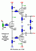
I'll post the diagram again with voltages and currents, but as I recall each tube is running a little over 2mA. This would be 12mA total, but this is divided up over three supplies, so each supply doesn't have to supply very much current.
Volume pot goes right at the input where the 1M grid leak resistor is located. In fact, you can remove the grid leak resistor. It was just a place holder in the diagram. I'll add this when I re-post later.
Do you mean the voltage of the transformer secondary? If so, then choose the 115V secondaries. This will rectify to a little over 160V (probably more given the light load on the transformers) giving you enough drop to use a choke and some resistors in a multi-stage filter that will be quite good and will lite the VR tubes.
+200V can come from a full-wave voltage doubler on the +100V supply and two VR tubes in series. Four glowing VR tubes altogether, two small transformers, some chokes and a few resistors. Relatively painless!!
If you want to get more sophisticated you can put tube CCSs on the CFs. This will reduce their contribution to the distortion. Many diyers on this forum would recommend this, but then that's a total of 5 tubes instead of 3.
As promised, here's the new diagram with volume control and bias currents.
I forgot to talk about the gain. The gain of each leg is less than 1, about 0.9. That is, measuring from either the + or - outputs to ground the gain is 0.9.
But, the gain when measured between the +/- outputs is twice that, or 1.8.
So, if your balanced amp needs 1Vp balanced signal input between the rails, then this guy will easily do the trick for less than 1Vp into the preamp.
So you want a tone control section? That can be switched in or out?
I forgot to talk about the gain. The gain of each leg is less than 1, about 0.9. That is, measuring from either the + or - outputs to ground the gain is 0.9.
But, the gain when measured between the +/- outputs is twice that, or 1.8.
So, if your balanced amp needs 1Vp balanced signal input between the rails, then this guy will easily do the trick for less than 1Vp into the preamp.
So you want a tone control section?
Attachments
Hi,
Is that currentdraw going to be enough for the VR tubes to regulate properly?
Cheers,
I'll post the diagram again with voltages and currents, but as I recall each tube is running a little over 2mA.
Is that currentdraw going to be enough for the VR tubes to regulate properly?
Cheers,
You're right Frank, I forgot to add the VR tube currents, say 10mA each.
The way this actually breaks down is, preamp only, both channels:
+200V - 8.6mA
+100V - 4.5mA
-100V - 8.8mA
or thereabouts.
So, add 10mA to each one for the VR tube and everything will regulate ok.
+200V - 18.6mA
+100V - 14.5mA
-100V - 18.8mA
Can be done with really simple supplies.
The way this actually breaks down is, preamp only, both channels:
+200V - 8.6mA
+100V - 4.5mA
-100V - 8.8mA
or thereabouts.
So, add 10mA to each one for the VR tube and everything will regulate ok.
+200V - 18.6mA
+100V - 14.5mA
-100V - 18.8mA
Can be done with really simple supplies.
- Status
- This old topic is closed. If you want to reopen this topic, contact a moderator using the "Report Post" button.
- Home
- Amplifiers
- Tubes / Valves
- Any schematics for balanced line driver using 6922?

